CNC Coil Winder 1 · Volume 1
The CNC Coil Winder: What It Is and Why the Shop Has One
1.1 A Machine That Counts, So the Maker Doesn’t Have To
Winding a coil is one of the oldest and most stubbornly manual jobs in electronics. A length of insulated copper wire is wrapped around a form, turn after turn, and the electrical behaviour of the finished part depends on getting the number of those turns right, on laying them neatly, and on keeping the tension even from the first turn to the last. Do it by hand and the work is slow, the count is easy to lose, and two coils wound on two different afternoons rarely come out the same. A CNC coil winder exists to take that job — the counting, the spacing, the steady tension, the exact repeatability — and hand it to a machine.
The machine documented in this deep dive is a benchtop CNC coil winder owned by this shop, one of three winders it runs (two computer-controlled units bought on eBay and one built in-house). “CNC” here means what it means on any other tool in the shop: computer numerical control — the operator enters numbers, and a controller drives motors to those numbers precisely and identically every time. On a milling machine the numbers are coordinates; on a coil winder they are turns, winding width, pitch, and speed. The result is the same in spirit. A part that used to depend on a skilled pair of hands now depends on a program, and the program can be saved and re-run tomorrow, or next year, and produce the same coil.
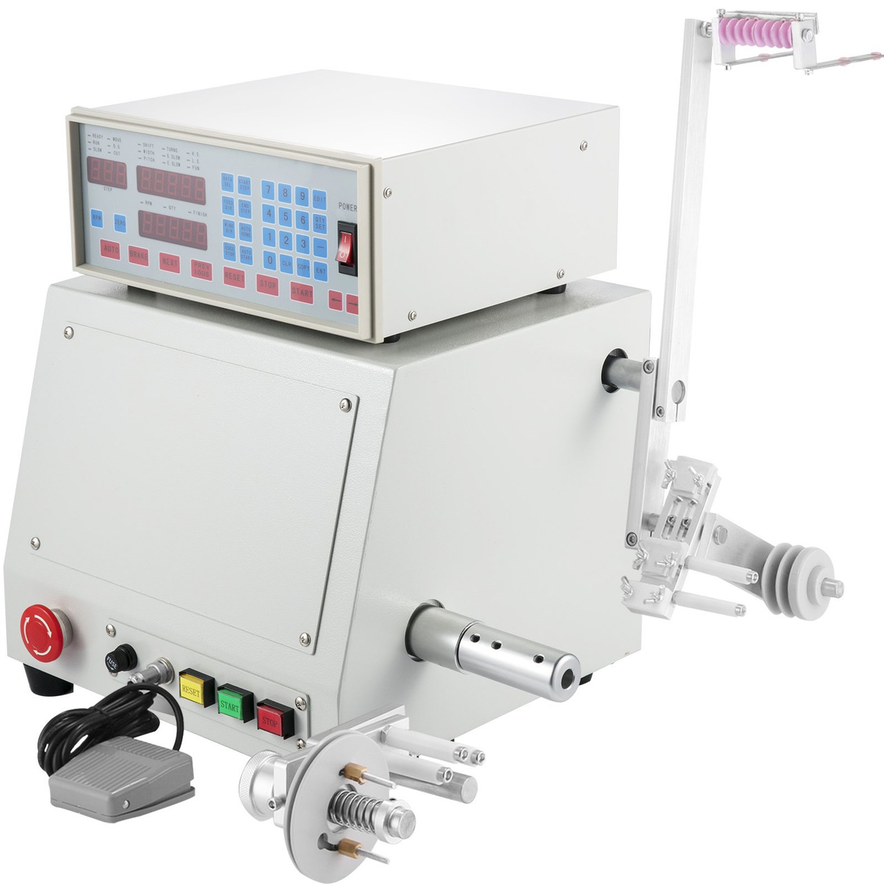
The figure shows the whole machine at a glance, and it is worth naming the parts now because the rest of this volume — and the three that follow — keep returning to them. The tall box with the red-and-blue keypad and the glowing red numeric displays is the controller. It sits on top of the heavier drive cabinet, which holds the spindle motor, the stepper driver for the traverse, the power supply, and a cooling fan. Poking out of the front of the cabinet is the spindle, the powered shaft that turns the coil. To the right, on the vertical arm, ride the supply spool of magnet wire, a tensioner, and a wire guide carried on the moving traverse. On the front panel are a foot pedal, an emergency stop, and start/stop/reset buttons. That is the entire machine: a thing that spins a form, a thing that feeds wire onto it, and a brain that keeps the two in step and counts.
This is a machine deep dive, not a theory deep dive. The physics of what a coil is — inductance, the magnetic field, why turns matter, why a coil “chokes” alternating current — lives in the companion reference dive “Coils and coil winding” on the Research site, and the craft of transformer winding will live in the coming “Transformers and transformer winding” dive. This series assumes the reader either knows that material or can reach for it, and concentrates instead on the thing standing on the bench: how it is built, what it can do, how to set it up, and how to keep it running. Where a winding concept needs stating to make the machine make sense — turns counting, pitch, tension, wire gauge — it is stated briefly here and cross-referenced there.
1.2 Why a Shop That Already Has Winders Wants a CNC One
A hobby electronics shop can wind coils several ways, and this one owns examples across the range. At the simplest end is a hand-cranked winder with a mechanical turns counter — a geared dial, like an odometer, that clicks over once per revolution. It is cheap, silent, and perfectly adequate for a dozen turns of stout wire on a big former. It is miserable for four hundred turns of hair-fine wire, where the hand tires, the count drifts, and a single overlapped turn spoils the layer. In the middle sit motorised bench winders that spin the spindle under a foot pedal and count electronically but leave the wire guiding to the operator’s fingers. At the far end is the CNC winder in Figure 1, where a second motor guides the wire automatically and the controller enforces the whole recipe.
The reason to own the CNC machine is not that the others cannot wind a coil; it is repeatability and unattended precision at high turn counts. Three things separate it from the manual tools. First, it counts to a resolution the hand cannot match — this class of controller resolves to a tenth of a turn — and it stops itself exactly on the target, so a 250-turn choke is 250 turns, not “about 250.” Second, it lays the wire itself: a stepper-driven guide walks back and forth along the coil in lock-step with the spindle, so each turn falls neatly beside the last instead of piling up in a lump. Third, it remembers. A wind that took twenty minutes to dial in the first time can be saved as a numbered program and recalled in seconds, so the tenth transformer of a batch matches the first. For anyone who winds the same part more than once — a run of matched inductors, a set of transformers for an amplifier, a batch of pickup coils — that memory is the whole point.
It is worth being clear about when the CNC machine is not the right tool, because owning one does not make the simpler winders obsolete. A handful of turns of thick wire on a large air-core form is faster to do on a hand-crank winder than it is to set up as a program; the CNC machine earns its setup time only when the count is high, the wire is fine, the wind is multi-layer, or the part is going to be made more than once. A shop that keeps all three classes of winder — hand-crank, motorised, and CNC — is not being extravagant; it is matching the tool to the job. The CNC winder’s sweet spot is precisely the work that makes hand-winding tedious and error-prone: the four-hundred-turn choke, the matched pair of common-mode windings, the small transformer that has to be reproducible. That is the work this machine was bought for.
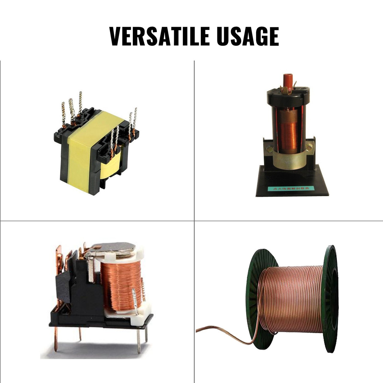
The parts in Figure 2 map onto real jobs in a maker’s electronics work. The small transformers are the daily bread of switch-mode power supplies, audio and isolation duty, and small mains transformers; winding them means putting a primary and one or more secondaries onto a bobbin with defined turns ratios, and the CNC machine’s saved programs make a multi-winding part practical. The tall high-turn coil is the sort of thing an inductor or a spark/ignition coil needs — thousands of turns of fine wire, exactly the case where hand-counting fails. The common-mode choke needs two identical windings laid the same way, which the machine can reproduce turn-for-turn. And the plain wound spool is a reminder that the machine is also just a very good way to move a precise length of wire onto a form under known tension. The theory behind each of these applications — where inductors and transformers are used and why — belongs to the reference dives; the machine is what turns the design into a physical part.
1.3 What “This Machine” Is
The unit in this shop was bought on eBay. Listings of this kind are usually for the same broad product: a benchtop computer-controlled coil winder, sometimes badged as an “M100” or simply as a “Computer CNC Automatic Coil Winding Machine,” sold under a rotating cast of brand names but built to a common pattern. It is important to be honest about the limits of what can be stated from a general listing, so this dive separates two kinds of fact. The class of machine is well documented and described here accurately from the manufacturers’ and resellers’ own specifications. The specific unit’s exact configuration — the precise motor rating, the serial and firmware, any options fitted, and the condition of a used purchase — is confirmed only from the machine itself, and those points are left as clearly marked owner’s slots to be filled from the bench.
For the class, the shape is consistent. The spindle is driven by a substantial motor — vendors quote figures in the several-hundred-watt range for this size, enough to spin a loaded bobbin briskly and to hold speed against the drag of the wire — and it turns at up to a few thousand RPM. The traverse that guides the wire is driven by its own stepper motor through a leadscrew, and the two are coordinated by the controller so that the guide advances by one wire diameter for every revolution of the spindle, laying a close-wound layer automatically. The controller is a dedicated microcomputer with a numeric keypad and several LED numeric displays, and it stores a large library of winding programs — commonly quoted as up to 999 — in non-volatile flash memory that survives power-off. The wire itself runs from a supply spool on a dereeler (a spool holder that pays out wire smoothly), through a tensioner that keeps it taut, to the moving guide and onto the bobbin. The machine handles a wide range of wire, from hair-fine enamelled copper up to a little over a millimetre in diameter, and a winding width and bobbin diameter of around 100 mm — the origin of the “M100” name. These figures, and the specifics of each subsystem, are laid out in detail in the next volume.
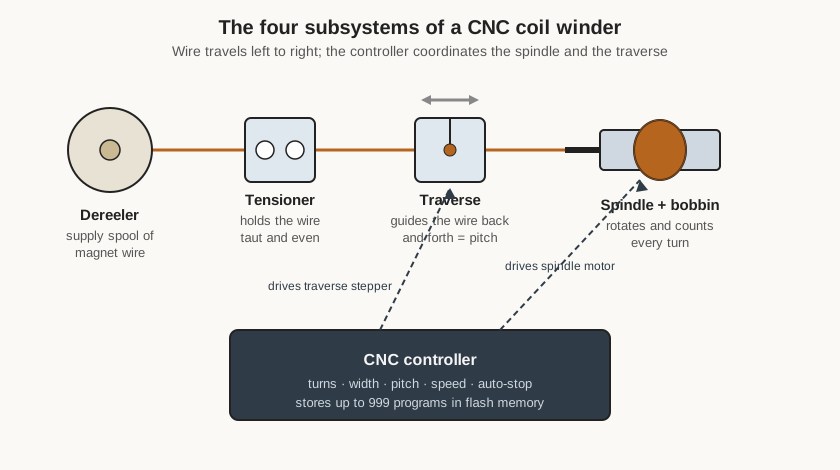
Figure 3 is the mental model to carry into the rest of the series. Whatever the badge on the front, a CNC coil winder is these four blocks: a spindle that rotates and counts, a traverse that guides the wire and sets its pitch, a tensioner and dereeler that deliver the wire evenly, and a controller that ties them together and remembers the recipe. Everything specific — the keypad legends, the motor ratings, the mounting of the arm — hangs off that skeleton.
1.4 Where It Fits in the Shop
The winder lives in the shop’s Coil Winders group alongside its two siblings: a second CNC unit, also bought on eBay, and a homemade CNC winder built in-house to the same principles. Having three is not redundancy so much as coverage. The two commercial machines carry the routine, repeatable production — the batches of inductors and transformers where their saved programs earn their keep — while the homemade unit is a platform for experiments and for winds that fall outside a boxed machine’s assumptions. This volume set documents the first commercial machine; its sibling and the homemade build have their own dives.
Beyond the winders themselves, the machine dovetails with the shop’s broader electronics work and with the reference material on the Research site. A coil or transformer is rarely an end in itself; it is a component in a power supply, a filter, an amplifier, a radio, or a piece of test gear. The winder is where a value computed on paper — so many turns on such a core for a target inductance, or such a turns ratio for a transformer — becomes a real part that can be soldered into a circuit. For the design side of that work, the “Coils and coil winding” reference dive covers how to choose a core, calculate turns for a target inductance, and pick a wire gauge, and the coming “Transformers and transformer winding” dive does the same for transformers. This deep dive picks up where those leave off: the design is done, the numbers are known, and the job now is to get them wound. The next volume opens up the machine that does it.
Comments (0)