CNC Coil Winder 2 · Volume 4
CNC Coil Winder 2 — Reference: specifications, maintenance, and links
4.1 Specifications at a glance
The table below collects the specifications of this machine’s class — the imported 0.03-1.2 mm benchtop CNC coil winder built around a Minsu-Automation CNC-200A-class controller, of which the eBay unit (item 406920548529) is one example. The specific listing text for that item was not reachable at the time of writing, and eBay item numbers for these machines are relisted frequently, so the values here are drawn from the identical, well-documented machine class rather than invented for this one unit. Anywhere the owner’s actual unit may differ — motor wattage, exact wire ceiling, controller firmware, included accessories — the value is marked as an owner’s slot to be read from the machine’s own plate.
Table 1 — Specifications at a glance
| Parameter | Typical value for this class | Owner’s unit |
|---|---|---|
| Windable wire diameter | 0.03-1.2 mm (some large-torque variants to 2.0 mm) | owner’s slot — confirm from plate |
| Max winding width | ~108 mm (4.3 in) | owner’s slot |
| Max former/framework diameter | ~200 mm (7.9 in) | owner’s slot |
| Max spindle speed | ~6000 rpm / circles·min⁻¹ | owner’s slot |
| Spindle motor | Brushless DC, ~400 W (600-750 W large-torque versions) | owner’s slot |
| Traverse drive | Stepper motor + leadscrew, constant-current driver | owner’s slot |
| Controller | Minsu CNC-200A class, single-chip microprocessor | owner’s slot — note firmware ver. |
| Program memory | ~1000 steps, flash (battery-free retention) | owner’s slot |
| Turn-count resolution | 0.1 turn | — |
| Speed steps | up to 99 steps | — |
| Power input | Single-phase mains, ~100-240 V, ~600 VA max | owner’s slot — confirm 110/220 V |
| Product dimensions | ~317 × 305 × 406 mm | owner’s slot |
| Weight | ~35 kg (shipping) | owner’s slot |
| Included accessories | Machine + foot switch (varies by seller) | owner’s slot — list what came with it |
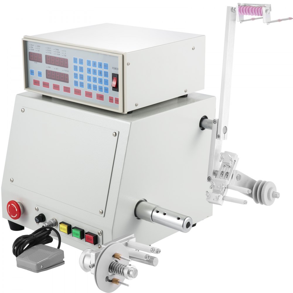
The single most useful reference for day-to-day operation is not this table but the controller manual — the CNC-200A user manual (versioned, e.g. H8681/3) documents every panel key, the SHIFT/WIDTH/PITCH/TURNS/S.SLOW/E.SLOW/H.S./L.S. parameter set, the step-region memory model, and the installation and wiring. A copy of the manual for the owner’s exact controller revision should be kept with the machine, since minor firmware revisions change a few key behaviours.
4.2 Where this machine sits in the wire range
The 0.03-1.2 mm specification places this winder across most of the practically useful magnet-wire range for a model shop, from very fine signal wire up to fairly heavy power-transformer and choke wire. The chart below places that span on the wire scale with approximate AWG equivalents, which is the practical way to think about which coils naturally belong on this machine versus on the finer-dressed winder 1.
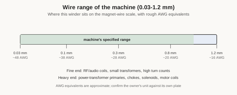
As covered in Volume 1, this is why the shop runs the two commercial winders as a complementary pair rather than as duplicates: winder 2 is kept dressed toward the heavier, wider half of this range, winder 1 toward the fine half, and the homemade winder takes the outliers neither commercial unit handles cleanly. The AWG equivalents on the chart are approximate and depend on the enamel build; the owner’s unit should be trusted against its own plate for the true wire ceiling.
4.3 Maintenance
A passive-tensioner bench winder is a low-maintenance machine, and most of what keeps it accurate is cleanliness and a few periodic checks rather than scheduled service. The routine below is generic to the class; the owner’s specific intervals and any modifications are owner’s slots.
Keep the wire path clean and smooth. The tensioner discs, guide eyelet, and any pulleys the wire touches wear grooves over time, and a grooved or nicked guide will score enamel and shed insulation into the winding. Inspect the surfaces the wire runs over and dress or replace them when they show wear. Keep enamel dust and stray wire whiskers out of the tensioner so the felt drag stays consistent.
Lubricate the traverse leadscrew lightly. The leadscrew and its guide rails should move freely; a light machine oil or grease appropriate to a leadscrew keeps the traverse smooth and prevents the stepper from losing steps under drag. Wipe off old, dust-laden lubricant rather than piling fresh on top of it, since grit on the leadscrew is what causes pitch inconsistency.
Check that the bobbin runs true and the arbor grips. Slipping or wobble is the most common cause of a bad wind, and both creep in as arbors and clamping hardware wear. Keep the arbor set clean and the clamping faces square.
Verify the turn count occasionally. The most important sanity check is that the displayed turn count matches reality. Wind a known number of turns onto a test former, count them (or measure resistance against the known wire), and confirm the controller agrees. A count that has drifted points to spindle slip, a bobbin creeping on the arbor, or an encoder/feedback fault — worth catching before it corrupts a real job.
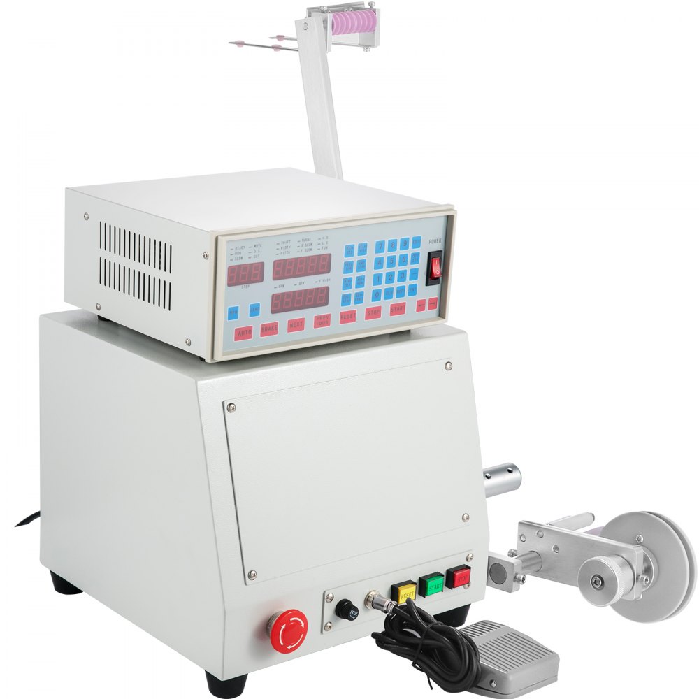
Respect the electronics. The controller integrates the stepper driver, the DC spindle controller and brake, and the power supply in one box with its own cooling; keep its vents clear and do not run it stalled against a jam. The CUT wire-break input and the foot switch are the machine’s safety interlocks in practice — keep them working. As with any mains machine, service the wiring and fuse per the manual and the local electrical code.
4.4 Troubleshooting
Most problems on a machine of this class fall into a short list, and nearly all of them point back to the mechanical setup rather than the electronics. The following are the common ones and where to look first.
The turn count does not match the coil. Almost always this is slip: the bobbin creeping on the arbor, or the arbor creeping on the spindle. The controller counts spindle revolutions faithfully, so a mismatch between displayed turns and actual turns is a mechanical grip problem. Re-seat and re-clamp the bobbin, check the arbor fit, and re-run the turn-count sanity check from the maintenance section. If grip is sound and the count still drifts, suspect the spindle encoder/feedback and consult the controller manual.
Turns pile up or leave gaps instead of lying flat. This is a PITCH or tension issue. If PITCH is set smaller than the wire’s true overall diameter, turns crowd and climb over one another; if larger than intended, gaps appear. Measure the actual enamelled wire diameter with a micrometer and set PITCH to that. If the pitch is right but turns still wander, the tension is too low, the bobbin is running out (wobbling), or the wire is approaching the guide at an angle rather than squarely.
The wire breaks or stretches. Too much tension, a nicked or grooved guide or tensioner disc scoring the wire, or a spool that binds and jerks. Back off the tensioner, inspect and dress the surfaces the wire runs over, and confirm the spool pays off freely. Fine wire is unforgiving here — the CUT indicator stopping the wind is the symptom, the wire path is the cause.
The traverse stalls, stutters, or loses position. A stepper on a leadscrew loses steps when it meets more drag than its current can overcome: dry or gritty leadscrew, a binding guide rail, or debris. Clean and lightly lubricate the leadscrew, confirm the rails move freely, and check the traverse drive current setting in the controller if the manual exposes it.
The controller behaves unexpectedly around stops and restarts. Recall that the machine preserves the fractional part of the turn count across a fixed-point stop and zeroes only the integer part on restart; a step chain that seems to “lose” or “gain” a fraction of a turn at a tap is usually this behaviour working as designed. Re-read the CNC-200A manual’s winding-execution section for the exact restart semantics of the owner’s firmware revision.
4.5 Accessories and consumables
A working winder needs more than the machine. The standing kit around this unit typically includes a set of arbors and mandrels sized to the shop’s common bobbin bores (this machine’s arbor set skews larger than winder 1’s, matching its heavier-coil role); spare tensioner felts or discs, which are wear items; start posts, tape, and sleeving for anchoring and dressing leads; interlayer insulation (polyester film, tape, or paper) for layered and multi-section windings; and a stock of enamelled magnet wire in the gauges the machine is dressed for. On the measurement side, an LCR meter for inductance, a milliohm-capable meter for winding resistance, a micrometer for verifying wire diameter, and a small spring scale for setting tension are what turn a wound part into a verified part. The foot switch that ships with the machine is itself effectively a consumable-adjacent accessory — worth having a spare, since a dead foot switch takes hands off the work.
4.6 Buying and receiving a used imported winder
Because this unit came used through eBay rather than new from a distributor, a few checks at receiving are worth recording. Confirm the mains voltage the unit is wired for (these ship in both 110 V and 220 V forms, and an imported unit may be set for the seller’s region), and confirm the controller firmware revision and that a matching manual is available. Verify the foot switch and any tensioner hardware actually arrived, since used listings often omit accessories. Run the turn-count sanity check before trusting the machine on a real job, inspect the wire path surfaces for wear left by the previous owner, and check the traverse and spindle for smooth, quiet motion. Anything found is recorded against the owner’s-slot entries in the specification table above.
4.7 Cross-links to the reference dives
This machine’s documentation is written to sit alongside two dedicated reference dives on research.fubsypoly.com/electrical-components, which carry the theory and practice this volume set deliberately does not repeat:
- Coils and coil winding — the physics and practice of the single coil: inductance and how turn count sets it, wire-gauge selection, layering and close-versus-spaced winding, self-capacitance, and measuring a finished coil. Reach for this dive for the derivation behind any TURNS or PITCH value entered into this machine, and for how to interpret the inductance and resistance readings taken to verify a wind (Volume 3).
- Transformers and transformer winding (coming) — the multi-winding case: primaries and secondaries, turns ratios, interleaving and insulation between windings, taps, and winding-order conventions. Reach for this dive when the job on the machine is a transformer, when a wind is broken into a chain of steps for multiple sections and taps, and for what interlayer/interwinding insulation to add during the pauses between steps.
Within the broader Model Shop collection, the winder also connects outward to the projects that consume its output: the coils and transformers wound here feed the shop’s electronics builds, restorations, and instrument work, and the same measurement habits (resistance, inductance, turns ratio) recur wherever a wound part has to meet a spec. Reading this machine’s dive alongside the coil and transformer reference dives gives both halves — the tool and the theory — that a finished, verified winding depends on.
The relationship is intended to be reciprocal. Those dives describe a modern programmable bench winder in the abstract; this machine — and the shop’s other winders — are the concrete instances they point to, and the owner’s-build slots left through these four volumes (the photographs of the actual unit, its real stored programs, and the coils it produces) are what fill in the specific examples. Within the Model Shop collection this machine also sits beside its two companions, CNC Coil Winder 1 (the shop’s finer-dressed commercial winder) and the Homemade CNC Coil Winder (the in-house build for the outlier jobs), and is best read as one member of that three-machine winding capability rather than in isolation.
4.8 Sources and further reading
- Minsu Automation CNC-200A coil winding machine controller user manual (versioned, e.g. H8681/3) — the authoritative reference for the controller’s panel, parameters, memory model, and wiring.
- VEVOR / MXBAOHENG / Happybuy / Gowe / SVOPES product listings and manuals for the “Computer CNC Automatic Coil Winder for 0.03-1.2 mm wire” — the specification basis for this machine class.
- eBay listing 406920548529 — the specific unit purchased (listing not reachable at time of writing; owner to confirm plate values).
- Coil-winding tensioner and dereeler references (e.g. mechanical disc/felt tensioners, fine-wire dereeler tension ranges) for setting the passive tensioner by wire gauge.
- The Model Shop’s Coils and coil winding and coming Transformers and transformer winding reference dives for the underlying theory and measurement practice.