Crossbar Rotating Stand · Volume 1
A Rotating Stand for a Crossbar Switch
1.1 The Job
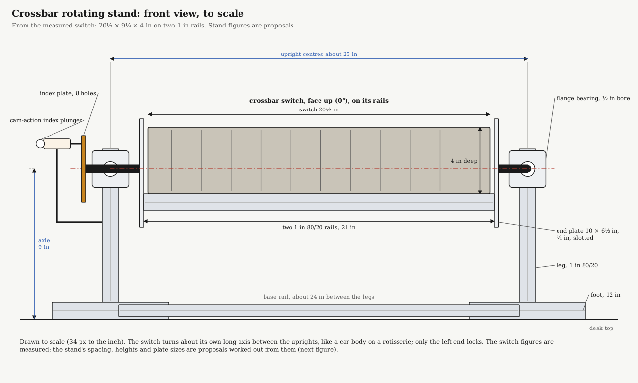
My Western Electric crossbar switch came out of a No. 755 crossbar PBX, and it is going to be rewired as the heart of My Crossbar PBX. That means hours of work on both faces. The bars, fingers and magnets are on the front. The bank terminals, where every wire is soldered, run along the top and bottom edges. The off-normal springs are on the ends. I measured mine at 20½ in long, 9¼ in across its face and 4 in deep. A switch of this kind weighs about 30 lb (calling315.com), and most of it is fine spring metal that should not be leaned on.
Lying flat on a bench, it shows one face and hides the rest. Propped on blocks, it can tip over. The answer is a stand that holds the switch in the air and lets it turn all the way round, locking at whatever angle the work needs.
The idea is to mount the switch on two 80/20 rails, carry the rails between two upside-down T stands, and let them turn through 360° with a positive lock every 45°.
1.2 Somebody Already Built This
This is a rotisserie. Car restorers mount a whole body shell between two end stands on a horizontal axle, so they can turn it on its side or upside down to work underneath, and lock it with a pin through a plate of holes. An engine stand does the same with one stand and a rotating head with a pin. A welding positioner is the powered version. Scaled down to a 30 lb switch, all three point at the same design:
- two end supports, so the load hangs between them and turns about its own long axis;
- a plain bearing at each end, with the load fixed to short shafts;
- an index plate and a pin, at one end only;
- a way to move the load relative to the axle, so it balances. Rotisserie makers call this adjusting the centre of gravity, and it is what separates a stand that turns with one finger from one that swings round and traps a hand.
1.3 The Design
The proposal has six parts.
- Two uprights. Each is an upside-down T of 80/20 extrusion: the top of the T is a foot lying on the desk, and the leg stands straight up. One goes at each end of the switch.
- A base rail joining the two feet. Without it the uprights can rack, and the two bearings drift out of line, which makes the shaft bind. With it, the stand is one rigid H-shaped frame that can be lifted as a unit.
- A flange bearing at the top of each leg, ½ in bore, 9 in above the desk. A two-bolt flange bearing bolts flat to the face of the extrusion with T-nuts. A plain bearing is simpler and stiffer than a pivot bracket, and it turns through 360° without stops.
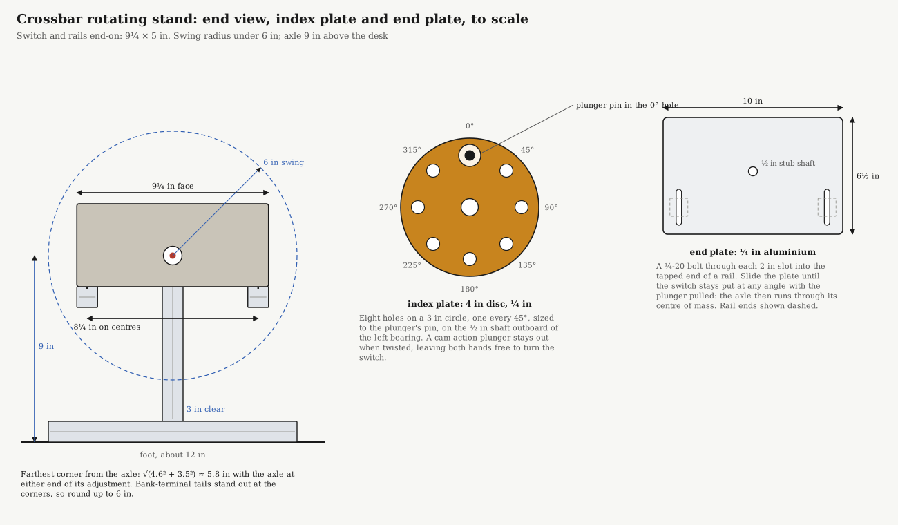
- Two end plates of ¼ in aluminium, 10 × 6½ in, one across each end of the two rails, each with a ½ in stub shaft (or a shoulder bolt) running in the bearing. A ¼-20 bolt goes through a 2 in slot in the plate into the tapped centre hole at the end of each rail, so the switch can be moved up and down relative to the shaft until it balances.
- An index plate: a 4 in disc with eight holes on a 3 in circle, one every 45°, fixed to the left-hand stub shaft outboard of its bearing.
- A spring indexing plunger on a small bracket on the left upright, pointing along the axle, whose pin drops into a hole in the index plate. A cam-action plunger stays retracted when its knob is pulled and twisted, leaving both hands free to turn the switch. They are standard catalogue items (Kipp, Misumi and McMaster-Carr all list them).
Only the left end locks; the right end just turns in its bearing. A friction knob can be added to either bearing later if the work ever needs angles between the 45° stops.
1.4 Three Things to Get Right
Balance. With the plunger pulled, a well-balanced switch stays at any angle it is left at. To set it, bolt the switch to its rails, hang it in the stand, pull the plunger, and slide the rails in the end-plate slots until it no longer turns on its own. The axle then passes through the centre of mass. An unbalanced 30 lb load a couple of inches off the axle will swing hard the moment the pin is pulled.
Height. Seen from the end, the switch and its rails sweep a circle as they turn, and the axle has to sit higher than the radius of that circle with room to spare for fingers. End-on, my switch and its rails make a block 9¼ in wide and 5 in high (4 in of switch on 1 in rails). With the axle anywhere in the 2 in of adjustment the end-plate slots give, the farthest corner is at most √(4.6² + 3.5²) ≈ 5.8 in from it. Rounding up to 6 in for the cut-off cable tails on the bank terminals, an axle 9 in above the desk leaves 3 in underneath.
Wiring. Until the switch is wired, it can turn as often as it likes. Once cables are on it, every full turn winds them up. Either limit it to half a turn each way, or bring the cable out through a hollow shaft at the right-hand end, as some rotisseries do for lighting.
1.5 The Rails Stay with the Switch
My switch’s mounting screws sit ½ in in from its two long edges, which is the centre line of a 1 in rail laid flush with the edge, so two 1 in 80/20 rails 8¼ in apart on centres take them directly, through T-nuts in the rails’ top slots. Because the rails bolt to the switch’s own mounting points, they do not have to come off again. When the switch moves to the back of the Strowger panel in My Crossbar PBX, the rails lift off the stand and bolt straight to 80/20 on the panel. The stand is then free for the next piece of equipment that needs it.
1.6 Parts (Proposal)
Table 1 — Parts (Proposal)
| Part | Qty | Notes |
|---|---|---|
| 80/20 extrusion, legs, 10 series (1 in) | 2 | About 9½ in, cut to put the bearing centre 9 in above the desk |
| 80/20 extrusion, feet, 10 series | 2 | About 12 in front to back, so the stand cannot tip with the switch turned on its side |
| 80/20 extrusion, base rail, 10 series | 1 | About 24 in, between the feet; sets the uprights about 25 in apart on centres |
| 80/20 extrusion, switch rails, 10 series | 2 | 21 in (¼ in past each end of the switch), 8¼ in apart on centres; ends tapped ¼-20; stay with the switch |
| Corner brackets or gussets, T-nuts, bolts | lot | Leg to foot, foot to base rail |
| Two-bolt flange bearing, ½ in bore | 2 | Bolted to the legs with T-nuts |
| End plates, ¼ in aluminium, 10 × 6½ in | 2 | Two 2 in slots for the rails, stub shaft hole 3½ in above the bottom edge. A job for the Shapeoko |
| Stub shafts or shoulder bolts, ½ in | 2 | Fixed to the end plates; the left one long enough to pass the bearing and carry the index plate |
| Index plate, ¼ in aluminium, 4 in disc | 1 | Eight holes on a 3 in circle at 45° |
| Cam-action indexing plunger and bracket | 1 | Pin diameter to match the index-plate holes |
1.7 The Switch’s Dimensions
Table 2 — The Switch's Dimensions
| Dimension | Value | Source |
|---|---|---|
| Length (along the axle) | 20½ in | measured on my switch |
| Face, across the bars | 9¼ in | measured on my switch |
| Depth, front to back | 4 in | measured on my switch |
| Mounting screws | ½ in in from the long edges | measured on my switch |
| Length and height in the literature | about 21 × 9 in | calling315.com (a 1970 Western Electric 10 × 10) |
| Weight | about 30 lb, mostly steel | calling315.com; not yet weighed |
| Room it had in its PBX | the 755A frame is about 24 in wide, 18 in deep and 72 in high uncrated; its upper section, where the two crossbar switches sat, takes 2 × 20½ in mounting plates | BSP 550-550-210 (1960); BSP 550-550-110 (1937) |
None of the 755A documents or the Bell Laboratories Record articles gives the switch’s depth or the position of its mounting screws, so those came off the switch itself with a rule. The literature’s length and height agree with the measurements to within half an inch.
1.8 My Build
Sources
- Western Electric 100-point crossbar switch size and weight: calling315.com.
- The switch itself and the exchange it is for: My Crossbar PBX, “My Switch”, telephones.fubsypoly.com.
- Dimensions of the switch: my own measurements, 7 November 2026.
Comments (0)