Prusa MK3S+ · Volume 2
The Machine in Detail — Motion, Bed, Extruder, and Electronics
2.1 Anatomy of a bed-slinger
To understand how the MK3S+ prints — and where its limits come from — one has to look at how it moves the nozzle relative to the object, because that is the whole game in FDM. The MK3S+ is a Cartesian machine: three independent linear axes, each perpendicular to the others, each driven by its own stepper motor. But the arrangement of those three axes is the specific thing that defines the i3 layout and gives it both its virtues and its one famous constraint.
The nozzle moves left and right along the X axis, riding on a short carriage that slides along two smooth steel rods. Those X rods, the motor, the extruder, and the nozzle are all carried on a single horizontal beam — the X gantry — which is not fixed: it climbs up and down the Z axis. The object being printed sits on a heated bed, and that bed slides forward and back on the Y axis. So of the three axes, two move the tool (X and Z) and one moves the workpiece (Y). This is the “bed-slinger” arrangement, and it is worth drawing.
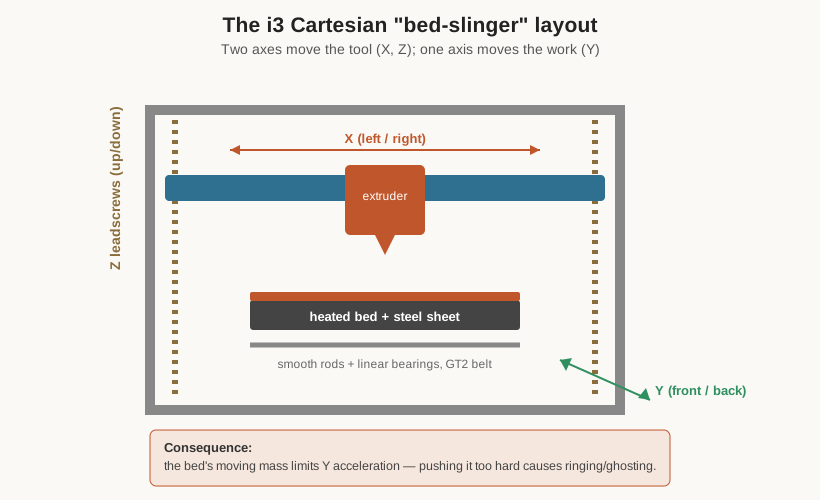
The great advantage of this layout is simplicity and serviceability. Each axis is independent and easy to reason about, the belts are short and accessible, and there is nothing exotic to go wrong. The famous consequence is the moving bed. As the print grows, the Y axis has to accelerate and reverse an increasingly heavy load — the bed, the sheet, and the object itself — many times a second. Sudden Y reversals shake a tall, top-heavy print, and pushing Y accelerations too hard shows up as ringing or ghosting: faint repeated echoes of sharp features rippling across the surface downstream of a corner. This is the single biggest reason a stock MK3S+ is not a fast printer in the modern sense, and it is exactly the problem that later CoreXY machines — which keep the bed still and move only the lightweight toolhead in X and Y — were designed to solve. On the MK3S+, the honest answer is to print at sensible speeds and let the machine’s excellent repeatability do the work.
2.2 The frame and the motion hardware
The MK3-generation frame was the point at which the i3 finally shed the last of its RepRap threaded-rod heritage. The main structure is a single piece of thick anodized aluminium, laser-cut and folded, forming the vertical portal that carries the Z axis and the gantry. The Y-axis base beneath it is likewise aluminium extrusion rather than smooth rod and threaded rod. The result is a rigid, repeatable frame that holds its geometry — a meaningful step up from the wobbly open-frame clones, and the foundation on which the machine’s consistency rests.
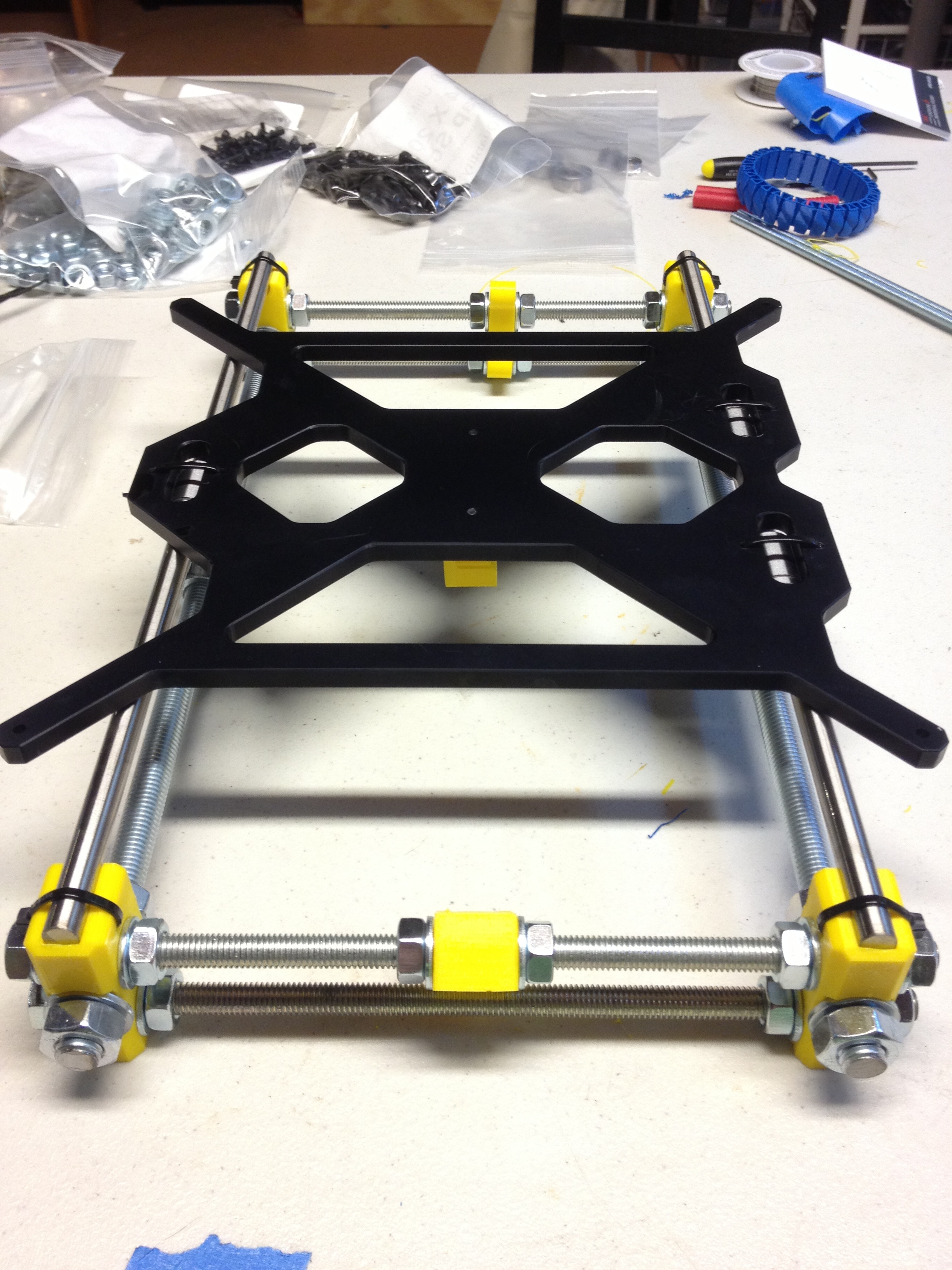
Motion on all three axes runs on smooth hardened steel rods with linear ball bearings (LM8UU-type), not the V-wheel-on-extrusion system used by some competitors. The X and Y axes are driven by GT2 toothed belts — a 2 mm-pitch reinforced rubber belt with fibreglass or steel cords to keep it from stretching — pulled by pulleys on the stepper motors. Belt tension on X and Y is therefore a genuine maintenance item; a slack belt shows up directly as dimensional error and ringing, and the firmware even reports measured belt status. The Z axis is different: it is driven by two trapezoidal leadscrews, one on each side, turned by two separate motors. Leadscrews are slow but precise and self-holding, which is exactly what the vertical axis wants — it needs to hold the gantry’s weight steadily and index it a fraction of a millimetre per layer, not move fast. The two independent Z motors also allow the firmware to sense and settle the gantry evenly at the top of each homing sequence.
The stepper motors themselves are NEMA 17 bipolar steppers, rotating in fixed 1.8-degree steps (200 per revolution). Because they are driven with fine microstepping, the effective resolution is far higher than 200 steps would suggest, giving smooth, precise, open-loop positioning without the cost and complexity of closed-loop encoders.
2.3 The removable magnetic spring-steel bed
If one feature explains why so many people fell in love with the MK3-generation machines, it is the bed. Earlier printers fought a perennial battle: prints stuck to the bed too well, and popping a finished part off a fixed glass or aluminium plate — with a scraper, a lot of force, and the occasional gouged thumb — was a genuine hazard and a source of damaged parts and beds.
The MK3S+ solves this with a removable magnetic spring-steel sheet. The heated bed proper is an aluminium plate with an embedded heater and an array of strong, heat-resistant magnets on its top surface, held under a smooth spring-steel plate that carries a coating. On top of that magnetic base sits a thin, flexible spring-steel sheet with a print surface bonded to it. Prints are made on the removable sheet. When a print finishes, the operator lifts the whole sheet off the magnets, flexes it like a saw blade, and the parts pop free — no scraper, no force on the machine, no gouges. Then the sheet snaps back onto the magnets, located by a small cutout, and the machine is ready for the next job. It is one of those ideas that seems obvious in hindsight and was genuinely transformative in practice.
The sheets come in interchangeable surfaces, and the choice matters because different plastics want different things from a bed:
- The smooth PEI sheet has a bonded layer of PEI (polyetherimide, a high-temperature engineering plastic that grips melted filament well when hot and releases it when cool). It gives a glassy, shiny bottom surface and grips small or spiky prints firmly. It is the classic PLA surface, and it can grip PETG too well — enough to tear a divot out of the sheet — so PETG on smooth PEI usually wants a release agent such as a wipe of glue stick.
- The textured powder-coated sheet has a PEI powder coating with a stippled, matte finish. It imparts an attractive textured bottom to prints, releases grippy materials like PETG and flexibles cleanly without a separation layer, and is the most forgiving all-rounder. Its texture is transferred to the first layer, so it is not the choice when a mirror-smooth underside is wanted.
- The satin sheet sits between the two in both texture and grip — a lightly textured surface that is a good compromise for mixed use.
Because the sheets are cheap, swappable in seconds, and double-sided, a shop typically keeps several and matches the surface to the material and the finish it wants on the part.
2.4 First-layer calibration and mesh bed leveling via SuperPINDA
A perfect first layer is the foundation of every successful print, and getting it right means the nozzle must be exactly the correct tiny distance above the bed across the entire print area — not just at one point. No bed is perfectly flat, and no bed is perfectly parallel to the plane the nozzle travels in. The MK3S+ handles this automatically with mesh bed leveling, and the sensor that makes it possible is the SuperPINDA.
The SuperPINDA is an inductive proximity probe mounted beside the nozzle on the extruder carriage. An inductive probe detects metal without touching it: it generates a small high-frequency magnetic field at its tip, and when that field approaches a conductive surface it induces eddy currents in the metal, which change the probe’s oscillation and trigger the sensor at a fixed, repeatable distance. Because the MK3S+ bed’s steel base is metal, the probe can sense exactly how far the nozzle carriage is above the bed at any XY position — without ever touching it, which means no risk of digging the nozzle into the sheet.
Before a print, the machine drives the probe to a grid of points across the bed — a mesh — and records the measured height at each one, building a map of the bed’s true shape: the low corner, the slight bow in the middle, the tiny tilt. During the first layer, the firmware then continuously adjusts the Z height to follow that map, so the nozzle keeps a constant gap above the actual surface even as that surface rises and falls by fractions of a millimetre. A slight warp that would ruin the first layer on a naive machine simply disappears into the mesh.
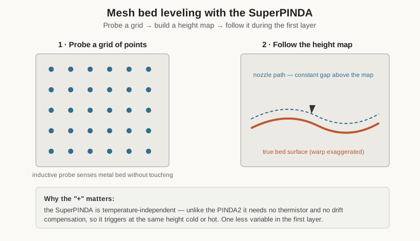
The ”+” in MK3S+ is largely this sensor. The earlier PINDA and PINDA2 probes were slightly temperature-sensitive — the trigger point drifted as the probe warmed up near the heated bed — and the PINDA2 carried a thermistor specifically so the firmware could compensate for that drift. The SuperPINDA uses better internal components that are inherently temperature-stable, so it needs no thermistor and no compensation: it simply triggers at the same height whether cold or hot. The practical result is a more consistent, more trustworthy first layer with one less variable to calibrate. Alongside the mesh, the operator sets a single Live Z (first-layer height) offset once, by hand, watching the first layer go down — a five-minute calibration that, once dialled in, holds indefinitely.
2.5 The Bondtech extruder and the E3D-derived hotend
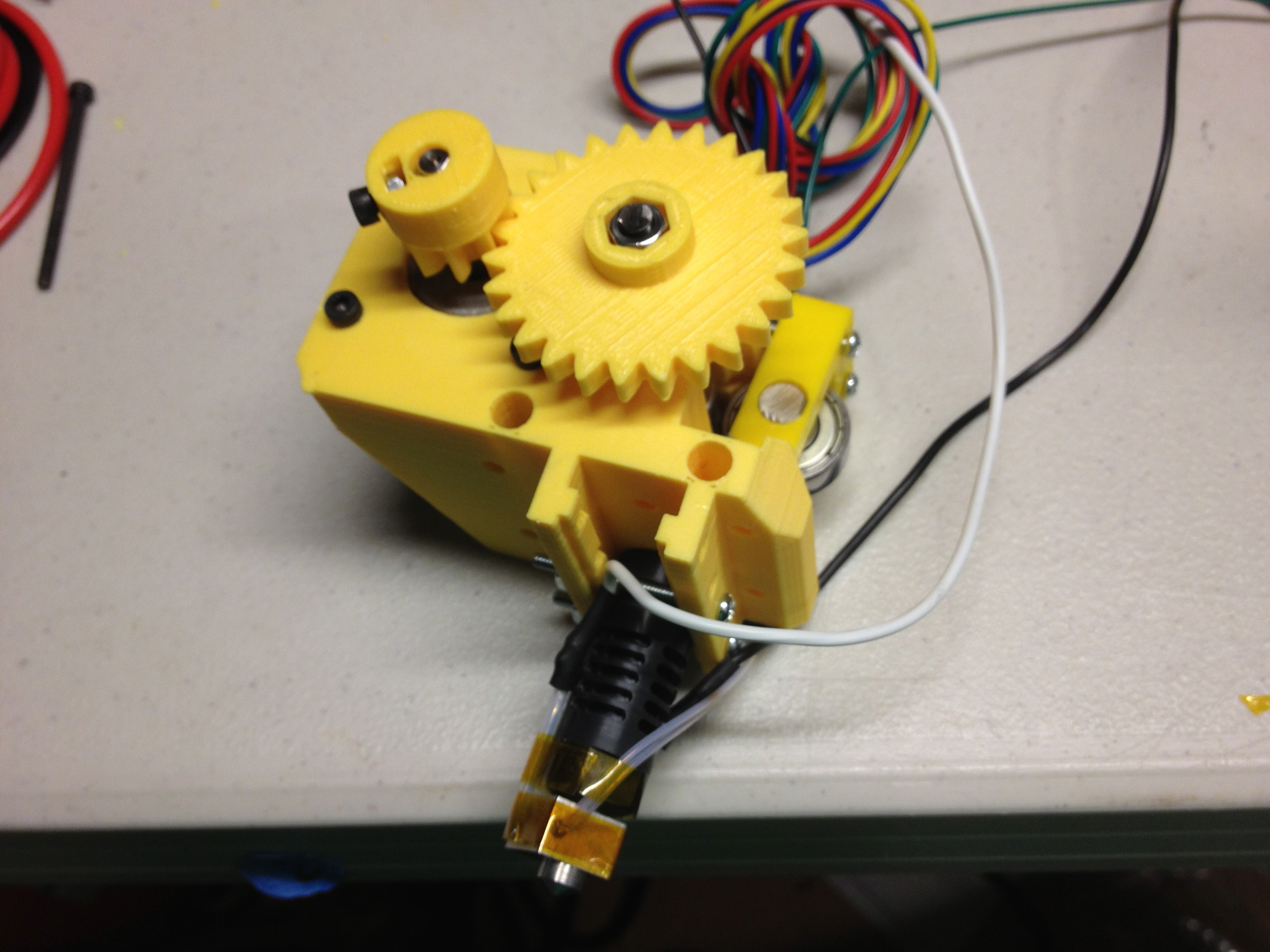
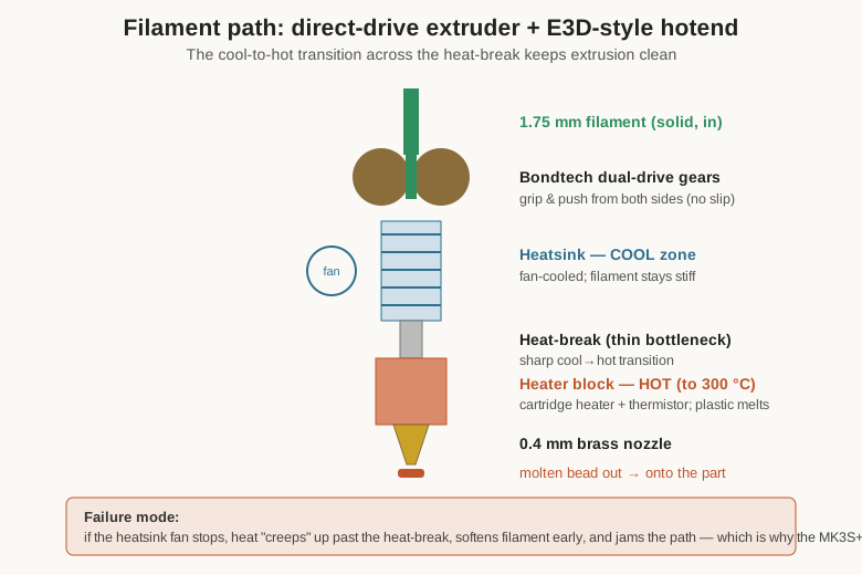
The extruder is the assembly that grips the filament and pushes it into the hotend, and the MK3S+ uses a direct-drive design — the motor and drive gears sit right above the hotend, on the moving X carriage, pushing filament the short distance straight down into the melt zone. This is opposed to a Bowtden setup, where the motor is fixed to the frame and pushes filament through a long PTFE tube to the toolhead. Direct drive puts more mass on the moving carriage (another reason not to sling the bed too hard), but it gives far better control over the filament, which is what makes the MK3S+ so competent with flexible materials and so reliable at starting and stopping extrusion cleanly.
The drive itself uses Bondtech dual-drive gears: two hardened, toothed gears, one on each side of the filament, both driven and geared together so they grip and pull the filament from both faces simultaneously. Single-drive extruders push from one side and rely on a passive spring-loaded idler on the other, which can slip under load; the Bondtech dual-drive shares the grip across two powered gears, giving a strong, consistent, slip-resistant feed. This is a large part of why the machine meters plastic so evenly and handles soft, squishy TPU filaments that a single-drive extruder would chew or buckle.
Below the drive gears sits the hotend, an E3D V6-compatible design — the de facto standard hobby hotend, which is why so many nozzle and upgrade options exist for it. Understanding its layout matters for maintenance. Filament enters through a heatsink kept cool by a dedicated fan; this cool zone keeps the plastic solid so it stays stiff enough to be pushed. It then passes through a thin-walled stainless heat-break — a deliberate thermal bottleneck — into the heater block, where a cartridge heater and a thermistor hold a precisely controlled melt temperature (up to 300 °C on this hotend), and out through the brass nozzle. The sharp transition from cool to hot across the heat-break is what makes clean extrusion possible; when it fails — usually because the heatsink fan stops or the assembly is poorly seated — heat “creeps” up into the cool zone, softens the filament too early, and jams the extruder. That failure mode is why the MK3S+ monitors its fans and halts if the hotend fan dies.
Two more sensors live on or near the extruder. The filament runout sensor detects the presence and, on this generation, the motion of filament entering the extruder; if the spool runs out or the filament stops feeding, the print pauses and the machine prompts for a reload. The MK3S+ carries the revised sensor introduced with that model, mounted so the filament path is straighter and TPU feeds more easily.
2.6 The Einsy RAMBo board and Trinamic drivers
All of this is coordinated by the Einsy RAMBo mainboard — an 8-bit controller built around an ATmega microcontroller. Eight bits is modest, and it is one of the reasons the MK3S+ cannot match the input-shaped speeds of its 32-bit successors. But it is thoroughly proven, well understood, and paired with a firmware (a Prusa fork of the open-source Marlin) that has been refined for years. For a machine whose whole appeal is dependability, a mature, boring, well-debugged controller is a virtue.
The component on that board that most defines the MK3S+ experience is the set of stepper drivers: Trinamic TMC2130. A stepper driver is the chip that actually feeds current to a motor’s coils to make it step; the TMC2130 is a sophisticated one, communicating with the mainboard over an SPI data bus rather than just taking dumb step pulses, and it brings two headline capabilities.
The first is quiet operation. The TMC2130 offers a mode Trinamic calls StealthChop, which shapes the coil current smoothly instead of chopping it abruptly. The audible result is dramatic: the shrill whine and buzz that made older 3D printers genuinely unpleasant to sit beside is replaced by a soft hum, so quiet that the loudest thing on a running MK3S+ is usually its cooling fans. For a shop where a printer may run for hours on a bench near people, that alone is worth a great deal. (For the highest-torque moves the firmware can switch a driver to the more forceful SpreadCycle mode, trading some quiet for reliability.)
The second capability is the clever one: sensorless homing and crash detection, using a Trinamic feature called StallGuard. A stepper motor working against a load draws a characteristic electrical signature; when the motor stalls — because the axis has reached its physical end, or because it has hit an obstruction — that signature changes in a way the TMC2130 can measure and report. The MK3S+ uses this two ways. For homing, it means the X and Y axes need no mechanical endstop switches at all: to find the origin, the machine simply drives each axis gently into its hard stop and detects the stall. Fewer parts, nothing to misadjust. For crash detection, the same mechanism runs during printing: if the toolhead collides with a lifted print, a stray clip, or a warped corner, the drivers detect the resulting stall, and the firmware stops and can re-home rather than grinding the motors and ruining the geometry for the rest of the job. It is a genuinely elegant use of the driver’s own sensing to add safety and simplicity at once.
Rounding out the electronics is the power-panic feature: the board watches the incoming mains, and if power is lost mid-print it uses the last of the reserve to save the exact print state to non-volatile memory, so the job can be resumed from where it stopped once power returns — turning a blackout from a ruined print into an inconvenience. Taken together — the quiet TMC drivers, the sensorless homing, the crash detection, the fan monitoring, the filament sensor, and power panic — these are the specific engineering choices that turned a conventional bed-slinger into the machine people trusted to run unattended. The next volume turns to how this shop has modified two of them.
Comments (0)