60 W CO2 Laser · Volume 3
The Support Systems — and Why None of Them Are Optional
3.1 The machine is the small part
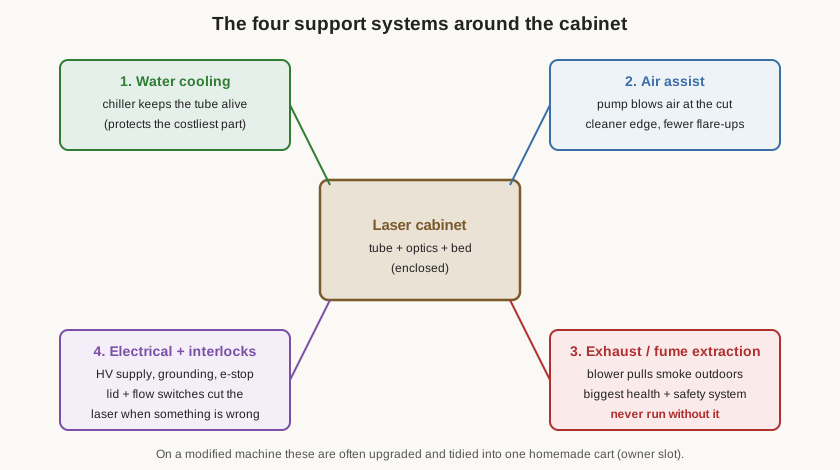
A newcomer looks at a laser cutter and sees the cabinet with the moving head. An experienced owner sees the cabinet as one node in a small network of services: a chiller humming beside it, an air pump ticking away, a blower dragging smoke down a duct and out of the building, and a web of interlocks watching that all of it is working before the tube is ever allowed to fire. These are the support systems, and the single most important lesson of owning a CO2 laser is that they are not accessories. They are the difference between a machine that runs safely for years and one that cracks its tube, fills the room with toxic smoke, or catches fire. The four of them — water cooling, air assist, exhaust, and the electrical and interlock story — and how they are upgraded and integrated on a modified machine like this one.
3.2 Water cooling: the tube dies without it
The glass CO2 tube must be water-cooled every second it fires, and this is the most unforgiving rule in the whole system. The high-voltage discharge inside the tube generates a great deal of heat in the glass. Water flowing through the tube’s jacket carries that heat away; if the water stops — a dead pump, a kinked hose, an empty reservoir, an operator who forgot to switch the chiller on — the glass heats unevenly and cracks, sometimes within seconds. A cracked tube is not repairable; it is a several-hundred-dollar consumable turned to scrap by one lapse. There is no version of running a CO2 laser without cooling, not even for a quick test.
There are two common ways to provide the cooling. The simple, cheap approach is a bucket and pump: a submersible aquarium-style pump sitting in a bucket of water, pushing it through the tube and back. It works, and it is how many machines start life, but it has two weaknesses. It offers no temperature control — the water slowly warms as the machine runs, and on a hot day it can climb too high — and it gives no protection if the pump fails. The better approach, and a near-universal upgrade, is an industrial water chiller. The entry-level CW-3000 is essentially a tidy pump-and-radiator that holds the water near ambient temperature; the refrigerated CW-5000 or CW-5200 actively holds the water at a set temperature regardless of the room, and includes alarms and, importantly, temperature and flow monitoring. For a tube that lasts longer and performs more consistently when kept in a stable window, a refrigerated chiller is money well spent.
Temperature matters in both directions. The published guidance for these tubes is a coolant flow of roughly 2 to 5 litres per minute and a water temperature kept in a moderate band — commonly cited as somewhere around 18 to 22 degrees Celsius, and in any case well within a 10 to 40 degree range. Too warm and the tube’s output and life suffer. Too cold — below the room’s dew point — and condensation forms on and inside the tube, which is its own path to trouble. The coolant itself should be clean; distilled or de-ionised water is standard, sometimes with an appropriate additive, precisely because tap water leaves mineral deposits and grows algae inside a tube that is very hard to clean.
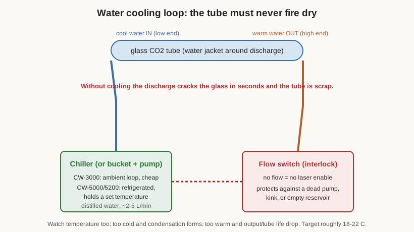
Because forgetting the water is so catastrophic and so easy, the cooling system is guarded by a flow switch: a small sensor in the water line that closes a circuit only when water is actually moving. That circuit is wired into the laser’s enable chain, so that no flow means no fire. It is the cheapest insurance on the machine and one of the first interlocks any careful owner confirms is present and working. Stock machines sometimes omit it; adding one is a standard part of a safety upgrade.
A few practical details separate a cooling loop that just works from one that keeps working. The water should enter at the low, output-mirror end of the tube and leave at the high end, so that any bubbles are swept out rather than collecting against the glass — an air pocket sitting on the discharge is a local hot spot and a crack waiting to happen, which is why owners “burp” the lines of trapped air when first filling. The reservoir or chiller should hold enough water that it does not warm quickly during a long job, and the loop should be checked for the slow failures that creep up over months: a hose stiffening and kinking, a fitting weeping, algae or mineral film clouding the water. Because the entire cooling system is what stands between the machine and a scrapped tube, it repays being built deliberately rather than thrown together from the cheapest pond pump and a length of tubing.
3.3 Air assist: cleaner cuts and fewer fires
The second system blows a stream of air directly at the point where the beam meets the material. This is air assist, and it does two valuable things at once. First, it clears smoke and vaporised material out of the cut kerf so the beam reaches the bottom cleanly instead of scattering through a haze of its own smoke — the result is a faster, deeper, cleaner cut with less charring on the edges. Second, and just as importantly for safety, it blows out the small flames that constantly try to start at the cut, especially in wood and acrylic. A cut without air assist tends to flare up; a cut with a good jet of air stays a controlled burn. Air assist is therefore both a quality tool and a fire-prevention tool.
The air comes from an air pump or small compressor feeding a hose to the nozzle in the cutting head. A modest diaphragm pump is enough for engraving and light cutting; more serious cutting benefits from a stronger, regulated supply so the pressure can be tuned to the job — gentle for delicate engraving, where too much air scatters the beam and lifts light material, and firm for thick cutting, where it clears the kerf and knocks down flames. A regulator and a moisture trap are common additions, because water or oil carried into the head from a compressor will foul the lens. Upgrading the stock nozzle to a better-designed air-assist head that directs the air tightly around the beam is one of the more rewarding optical modifications.
3.4 Exhaust and fume extraction: the biggest safety system
If water cooling protects the machine and air assist protects the cut, exhaust protects the operator, and it is the single most important safety and health system on the whole machine. Every cut and engrave produces smoke, and that smoke is not harmless: it is a mix of fine particulate and a chemical soup that depends entirely on the material. Burning wood and acrylic alone produces irritating, unpleasant, and unhealthy fumes; the point of the exhaust system is to capture all of it at the source and get it out of the breathing space.
A proper setup pulls air through the sealed cabinet with a blower — typically an inline duct fan or a squirrel-cage blower — and pushes it out of the building through ducting, exactly like a powerful range hood. The cabinet is arranged so that fresh air enters at one side and is drawn across the bed and out, so smoke never lingers over the work or leaks into the room. Getting this right means a blower with enough airflow for the size of the cabinet, short and smooth ducting, and a genuine outdoor exit — not merely blowing fumes into a garage or another room. Some shops that cannot vent outdoors use a large fume filter with activated carbon and particulate stages, but these are expensive, consumable-hungry, and only as good as their maintenance; venting outdoors is simpler and more reliable where it is possible.
Sizing and routing the exhaust well matters as much as having one. The blower must move enough air for the cabinet’s volume to clear smoke faster than it is produced; too weak a fan lets a haze build over the work, which both spoils the cut (the beam scatters through its own smoke) and lets fumes escape into the room. The ducting should be as short, straight, and smooth as practical — every bend and every run of flexible corrugated hose adds resistance that robs the blower of airflow. A sealed cabinet with a defined inlet is what lets the blower actually pull across the bed rather than sucking in room air through gaps, so the smoke is captured at the source. Where the duct exits, it should genuinely reach outdoors and away from windows and neighbours, not merely dump into an attached garage. Owners often add a damper or blast gate to close the duct when the machine is idle, keeping cold draughts and pests out.
Two rules follow from all this. First, never run the laser without the exhaust running — a cut that seems small still produces fumes and, on the wrong material, can produce dangerous ones. Second, the exhaust is what makes material choice a life-safety matter rather than a quality preference, because some materials (covered in the reference volume) produce genuinely toxic and corrosive gases that no reasonable exhaust should be asked to handle in the first place. The exhaust is the safety net; it is not permission to cut anything.
3.5 Electrical and interlocks
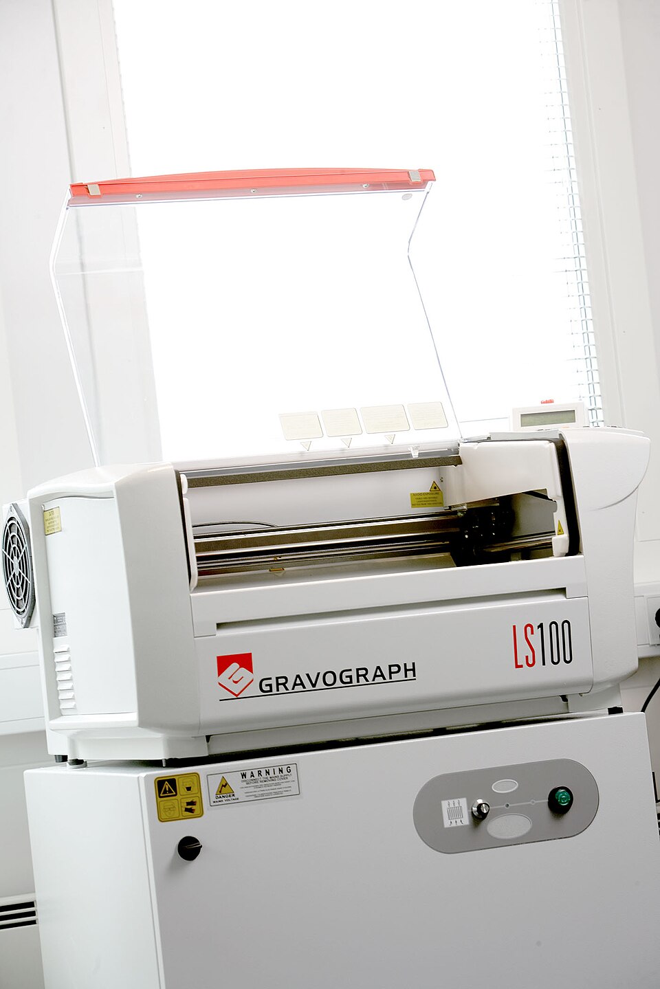
Underlying all of this is the electrical system, and a CO2 laser presents two distinct electrical hazards that deserve respect. The obvious one is ordinary mains wiring for the chiller, blower, air pump, and controller — routine, but it should be done cleanly, properly grounded, and ideally on a circuit that can be killed at one switch. The less obvious and more dangerous one is the high-voltage side: the LPSU and tube run at 15 to 20 kilovolts, energy that can kill and that lingers in capacitors after the machine is switched off. The high-voltage bay is treated in the safety volume with the seriousness it deserves; the short version is that it is worked on de-energised, discharged, and never casually.
Tying the whole system together are the interlocks: sensors that break the laser’s enable circuit unless it is safe to fire. The two essential ones have already appeared — the flow switch (no water, no fire) and the lid switch (open cabinet, no fire, so the operator is never exposed to the beam). A well-set-up machine adds an emergency stop that cuts everything at a slap, and often a key switch and an ammeter to read the tube current directly. Interlocks are cheap, and on a stock Chinese machine they are frequently the weakest area — sometimes bypassed at the factory to make the machine “just work.” Restoring and improving them is one of the most important, least glamorous modifications an owner makes, and it is entirely in keeping with treating the machine as a serious tool.
3.6 Pulling it together on a homemade cart
On a modified machine, these four systems are rarely left as a pile of separate boxes trailing hoses across the floor. The natural end-point is to integrate them onto a cart — a rolling stand, built to fit, that carries the chiller, the air pump, and often the blower, with the ducting and cabling routed cleanly and the whole assembly movable as one unit. A good cart turns a sprawling, trip-hazard installation into a self-contained station: everything the laser needs travels with it, connections are short and permanent, and the machine can be rolled aside when the shop needs the space. It is also where an owner’s own priorities show most clearly — where the chiller lives, how the exhaust is routed, what interlocks and switches are added, whether there is bed lighting or an ammeter on the panel.
That homemade cart, and the specific way this machine’s support systems are built and upgraded, are exactly the owner-build details these volumes leave open rather than invent.
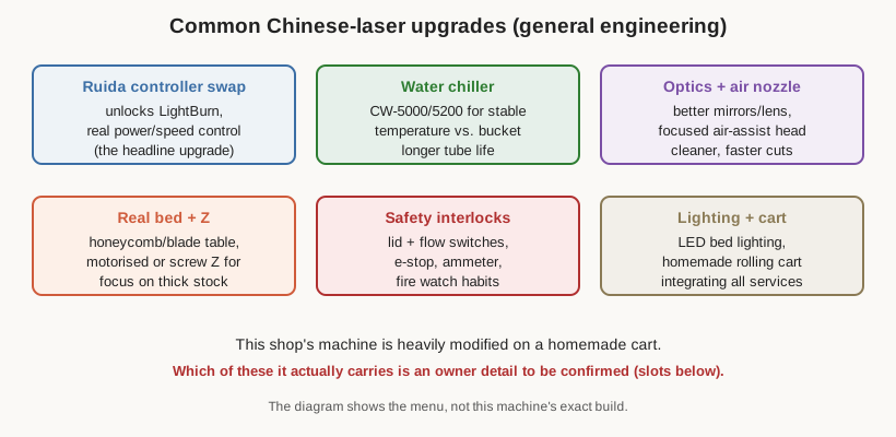
The recurring theme is worth restating because it is the whole point of the volume: a CO2 laser is a system. The cabinet cannot be understood, run, or upgraded in isolation from the water that keeps its tube alive, the air that keeps its cuts clean and its flames down, the exhaust that keeps its operator safe, and the interlocks that refuse to let it fire when any of those are missing. Skimp on the support systems and the machine will, sooner or later, teach the lesson the hard way. Build them well — and gather them onto a cart — and the laser becomes the dependable workhorse it is meant to be.
Comments (0)