HiTorque 3990 Mini Mill · Volume 2
HiTorque 3990 Mini Mill — The Machine in Detail
2.1 From the floor up
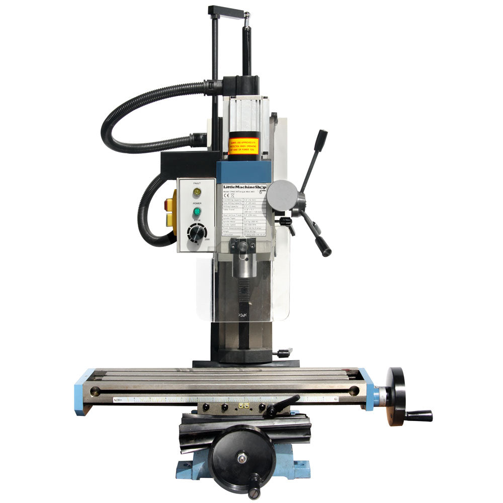
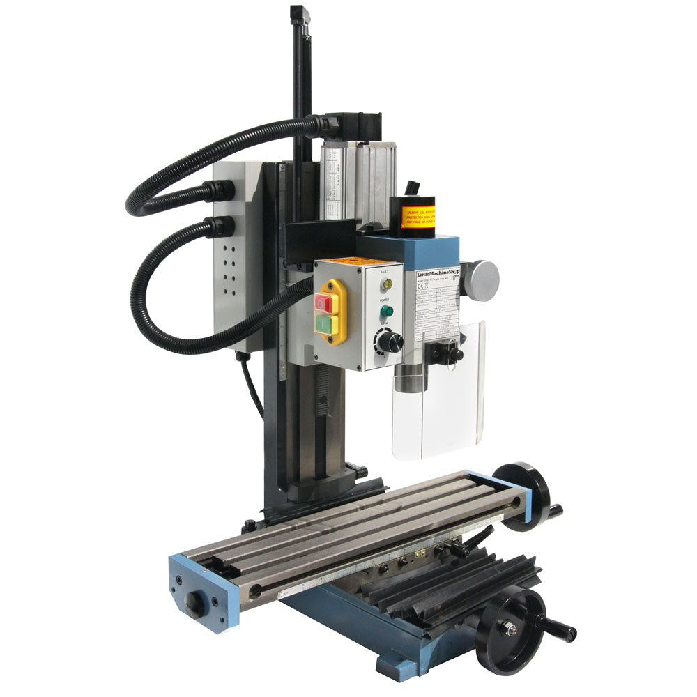
A milling machine is a stack of castings, each carrying the one above it and adding one degree of freedom. Understanding a mini mill means walking that stack from the bottom, because every source of accuracy — and every source of error — lives at one of the joints between castings. On the HiTorque 3990 the stack is: base, solid dovetail column, head, and within the head the quill and spindle; carried on the base and moving beneath the spindle are the saddle and table that provide the two horizontal axes.
2.2 The base and the column
The base is the machine’s foundation: a flat-bottomed iron casting that bolts to the bench and carries the vertical column at its rear. Its job is unglamorous but essential — to be flat, to be heavy enough to damp vibration, and to hold the column square to the table’s plane of travel. On a mini mill the base is also where the whole machine’s rigidity begins; a base that flexes or that is bolted to a springy bench will telegraph every bit of that movement into the cut as chatter and poor finish. The 3990’s base is drilled for mounting bolts, and the first thing this shop did on installation was to bolt it down solidly to a stiff bench, because an unsecured 56 kg mill walks under a heavy cut and loses accuracy long before it tips.
The column is the 3990’s defining structural feature. As noted in Volume 1, it is a solid, non-tilting dovetail column — a single heavy casting, not the round post or the tilting column of an older X2. Two things about it matter in daily use. First, it is a dovetail way: the head rides up and down the column on a machined dovetail slide with an adjustable gib (a tapered strip that takes up clearance between the sliding surfaces). A dovetail constrains the head in every direction except the one it is meant to move in, so unlike a round column the head cannot rotate as it travels — raise or lower it and the spindle stays pointed at the same X–Y position over the table. That single property removes one of the most infuriating errors on cheap mini mills, where a mid-job Z change quietly shifts the head and ruins hole alignment. Second, because the column is a fixed, thick-walled casting rigidly joined to the base, it deflects less under cutting load. The cost is that the head does not tilt, so cutting at a compound angle requires an angle vice or a tilting table rather than nodding the head — a trade this shop accepts gladly for the everyday rigidity and repeatability it buys.
2.3 The head, spindle, and taper
The head is the powered assembly that rides the column. It contains the motor, the spindle, the quill, and the feed mechanisms, and its weight is carried by an air spring (a gas strut) so that the head glides rather than drops when the coarse feed is released. That air spring is a genuine convenience and a small safety feature: on mills without one, the head is counter-balanced by a spring or simply held by the operator, and a slip can drop the head onto the work.
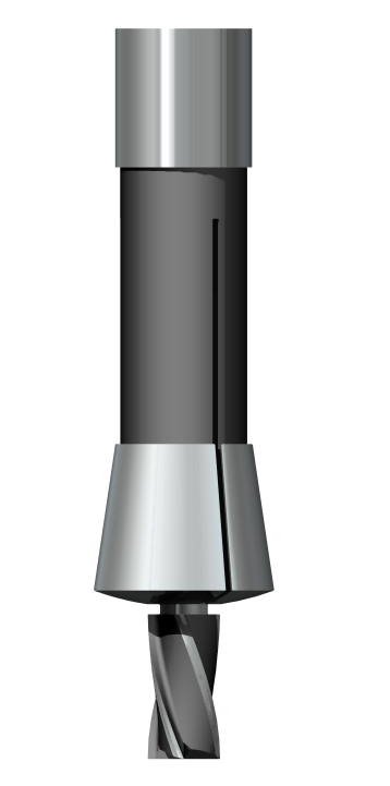
At the heart of the head is the spindle — the rotating shaft that holds and drives the cutter. The spindle’s business end is a precision internal taper, and the 3990 uses an R8 taper. R8 is worth understanding because it shapes how the whole machine is tooled. It is a shallow (about 16.5°) self-releasing taper originally designed by Bridgeport, with a 7/16-20 drawbar thread up the middle and a keyway near the top of the taper. A tool holder — a collet, a drill chuck arbor, an end-mill holder — is pushed up into the taper and pulled tight by a drawbar threaded down through the top of the spindle. The keyway stops the collet from spinning in the taper while the drawbar is tightened. Because R8 is self-releasing (the taper angle is steep enough that it does not lock solid), a light tap on the loosened drawbar frees the tool; contrast that with a Morse taper, which is self-holding and needs a firmer knock to break loose.
The alternative some mini mills use is MT3 — Morse taper No. 3. MT3 works, but R8 has two practical advantages that made it the right choice on the 3990. First, tooling availability: because R8 is the Bridgeport standard, R8 collets, holders, and accessories are everywhere and inexpensive. Second, collet range and convenience: R8 collets seat and release cleanly with the drawbar and cover the common end-mill shank sizes directly. For a shop that shares tooling philosophy with full-size equipment, R8 is simply the more useful taper.
2.4 The quill and the fine feed
Inside the head, the spindle runs in a sliding sleeve called the quill. The quill lets the spindle move up and down a short distance independently of the whole head, and it is controlled two ways. The coarse feed is a set of drill-press-style levers (a three-armed handle) that plunge the quill quickly — exactly what you want for drilling, where the motion is a fast in-and-out. The fine feed is a geared handwheel that advances the quill slowly and precisely, graduated to about 0.001 inch per division, for controlled downfeed when boring, spot-facing, or taking a measured plunge.
The distinction between moving the quill and moving the head on the column is important and is a common beginner confusion. Both change the spindle’s height (Z), but they are used differently: the head is dropped or raised on the column to set up the general working height and clamped there, while the quill is the fine, in-cut Z motion used during an operation. Good practice on a mini mill is to bring the head down so the job is done with the quill retracted or nearly so, because a long-extended quill is a cantilever — the further the quill sticks out, the less rigid the spindle is and the more it can deflect. Keeping the quill short and the head clamped is one of the quiet habits that separates clean cuts from chatter.
2.5 The X–Y table and travels
Beneath the spindle, two stacked castings give the horizontal motions. The saddle sits on the base’s ways and moves in Y (in and out, toward and away from the column); the table sits on the saddle’s ways and moves in X (left and right). Both ride on dovetail ways with adjustable gibs, and both are driven by a leadscrew and nut turned by a graduated handwheel. This is the classic cross-slide arrangement: turn the X handwheel and the whole table traverses left–right; turn the Y handwheel and the saddle (carrying the table) moves fore–aft. The combination lets any point on the table be brought under the spindle.
The 3990’s table is one of its selling points: 460 mm × 120 mm (18.1 in × 4.7 in), with three 12 mm T-slots running the long way for clamping. The travels are 300 mm in X, 130 mm in Y, and 270 mm in Z. The long X travel is genuinely useful — it means longer parts can be machined, or a part repositioned along its length, without unclamping. The T-slots accept standard T-nuts and hold-down clamps, or the mounting of a machine vice, which is how most work is actually held (Volume 4 covers workholding).
Each axis has backlash in its leadscrew, and each has a gib that can be adjusted to set the sliding friction. Both are tuning points rather than defects: the gibs are set tight enough to remove play but loose enough to move smoothly, and the backlash is measured so it can be compensated — a task the DRO makes almost irrelevant for positioning, since the scales read true table position regardless of the screw. That is the deep reason a DRO matters so much on this class of machine, and it is developed fully in Volume 3.
2.6 The brushless drive and variable speed
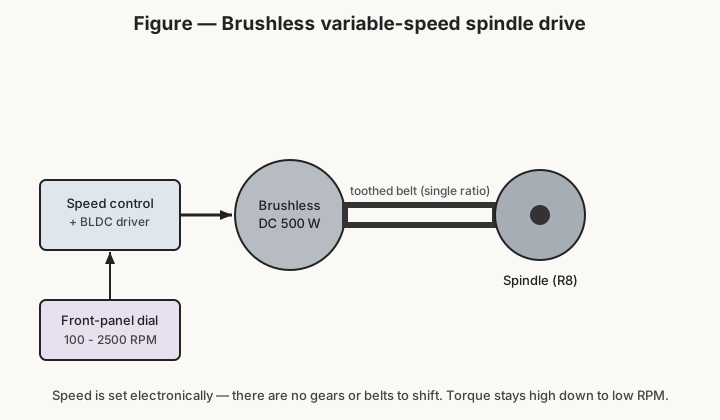
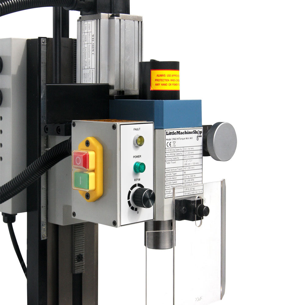
The 3990’s drive is the feature its name celebrates. A brushless DC (BLDC) motor rated 500 W (0.67 hp) turns the spindle through a single toothed belt. A brushless motor has no commutator brushes to wear or arc; instead an electronic controller energises the stator windings in sequence, sensing rotor position, which lets it deliver smooth torque and hold a commanded speed under varying load. In a mini mill that translates to three practical benefits over the old brushed-and-geared X2: it is quiet, it has no gears to strip, and it keeps usable torque at low rpm, which is exactly where a mini mill needs it for large cutters and steel.
Speed is set by a single dial on the front panel, continuously variable from about 100 to 2500 rpm. There is deliberately no gear or belt shifting — the controller simply runs the motor at whatever speed the dial commands, and the belt is a fixed single reduction between motor and spindle. That is a real ergonomic gain: on a two-range geared mill you stop, open a cover, move a belt or throw a lever, and re-check the speed every time a job needs a different rpm; on the 3990 you turn a knob. The one thing the operator still has to supply is judgement — the right rpm for the cutter diameter and the material — because the machine will happily let you run a cutter far too fast or too slow. Volume 4 covers choosing speeds and feeds.
2.7 Tramming the head
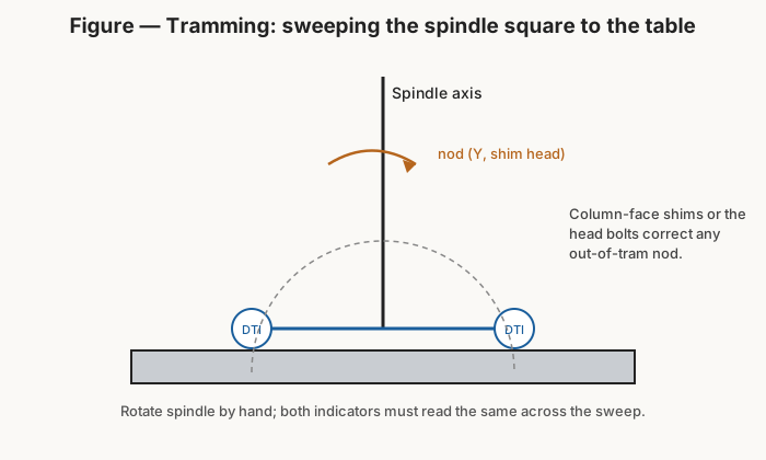
Because the head is fixed to a solid column, the spindle should be perpendicular to the table straight from the factory — but “should be” is not “is,” and any mill benefits from a periodic tram check. Tramming means verifying (and correcting) that the spindle axis is exactly square to the table surface, both side-to-side and front-to-back. If it is not, a face-milling cut leaves a shallow scalloped or dished surface instead of a flat one, and a squared-up block comes out very slightly out of parallel.
The check is done with a dial test indicator (DTI) mounted in the spindle on an arm, its tip touching the table well out from centre. Rotating the spindle by hand sweeps the indicator around a circle; if the head is square, the indicator reads the same at every point of the sweep. A difference between the left and right positions reveals a side-to-side error; a difference front to back reveals nod. On a solid-column mini mill, correction is a matter of the head-to-column mounting: loosening the head bolts and shimming or nudging as needed, or shimming the column-to-base joint for the front-to-back component. It is a fussy but infrequent job, and getting it right pays off on every flat surface the machine ever cuts.
2.8 Materials and capability
The last thing to understand about the machine in detail is the honest edge of what it can do. The 3990’s stated capacities — 16 mm end milling, 30 mm face milling, 13 mm drilling — describe the biggest tools it will turn, not the depth of cut it will take in one pass, and the difference is where material choice comes in.
In aluminium (and brass, plastics, wax) the mini mill is in its comfort zone. These materials cut with low force, clear chips easily, and let the machine run near its capacities with a light, steady hand. Facing aluminium with a fly cutter or a small face mill, slotting, drilling, and boring all go smoothly, and surface finish is good if speeds and feeds are sensible and the cut is kept lubricated or run dry-and-fast as the material prefers.
In mild steel the same machine is capable but must be respected. Steel cuts with much higher force, so the rule is light passes, correct (low) speeds, and steady feed: a few tenths of a millimetre depth with a modest-diameter end mill, spindle rpm dropped to suit the material, and cutting fluid to keep the edge alive. Pushed too hard — too deep a cut, too fast a feed, a dull cutter — a mini mill tells you immediately with chatter, a stalling spindle, or a snapped end mill, because it simply does not have the mass and power to bull through. Worked within its limits, though, the 3990 makes clean, accurate parts in steel; it just asks for patience the way every small machine does.
Harder materials (tool steel, stainless) are possible in small, careful cuts but sit at the machine’s limit and wear tooling quickly; they are the exception, not the routine. Knowing where that edge is — and staying just inside it — is the whole art of running a mini mill well.
It is worth naming the specific limits that set that edge, because they are structural rather than a matter of effort. The mass of the machine (56 kg) limits how much cutting force it can absorb before it flexes or chatters; the 500 W motor limits how much metal it can shear per second before it bogs; the dovetail ways and their gibs limit how much side load the slides can take before they deflect; and the cantilevered quill limits rigidity whenever it is extended. None of these is a defect — they are simply the physics of a benchtop machine — and every one of them is respected by the same remedy: lighter cuts, sharper tools, sensible speeds, and rigid, close work-holding. A mini mill run inside those limits is a precise and satisfying machine; run outside them it is a cutter-breaking source of frustration, and the difference is entirely in the operator’s restraint.
The rest of these volumes build on that understanding: first the DRO that tells you exactly where you are, then the operations that put the machine to work within its honest envelope.
Comments (0)