HiTorque 3990 Mini Mill · Volume 4
HiTorque 3990 Mini Mill — Using It
4.1 The four operations that do most of the work
Almost everything a mini mill is asked to do is a combination of four basic operations: facing, slotting, drilling, and boring. Learning the machine is mostly learning how to set up and run those four well within the limits of a small, light mill.
Facing is machining a flat surface. A cutter with a large flat cutting circle — a face mill or a fly cutter (a single-point tool swung in a circle) — is passed back and forth across the top of a workpiece, each pass overlapping the last, until the whole surface is cut to one plane. On the 3990, facing is the go-to first operation on any rough blank: it establishes a flat, known reference face that every later measurement and cut is taken from. The machine’s 30 mm face-milling capacity and its low-end torque suit it to a modest face mill or a fly cutter taking a light cut; the keys are a well-trammed head (so the face comes out flat, not dished) and a shallow depth with a steady feed.
Slotting is cutting a channel with an end mill, where the tool is buried to full width and cuts on its sides and end at once. It is the most demanding of the everyday operations because the cutter is fully engaged, so the force and the heat are highest and chip clearance is worst. On a mini mill, slots are cut in shallow steps — a fraction of the end mill’s diameter deep per pass — rather than plunged to depth in one go, and the feed is kept steady so the cutter neither rubs nor overloads. Keyways, pockets roughed to depth, and edges cut to a line are all slotting jobs.
Drilling puts a round hole through the work using a twist drill held in a chuck (or, for larger holes, a taper-shank drill in an arbor). The mill’s advantage over a drill press is position: the table and the DRO place the hole exactly where it belongs, not just roughly under the chuck. The 3990’s drill-press-style coarse quill levers make the plunge quick and natural, and its 13 mm drilling capacity covers most hole sizes; bigger holes are drilled undersize and opened up. Spotting the hole first with a stiff centre drill or spotting drill keeps the twist drill from wandering off the marked centre.
Boring enlarges and trues an existing hole to a precise diameter and location using a single-point boring head — an adjustable tool that takes a fine cut on the hole’s wall as the quill feeds down. Boring is how a hole is made both exactly round and exactly the right size, better than any drill can manage. It is a slow, careful operation well suited to the mini mill’s fine quill feed, and it is where the DRO’s ability to hold a datum and creep up on a dimension really shows.
4.2 Holding the work
No operation is any better than the way the work is held. A part that shifts under cutting force ruins the cut and can throw a cutter or the part itself, so workholding is the first thing to get right, and on the 3990 it comes down to three approaches.
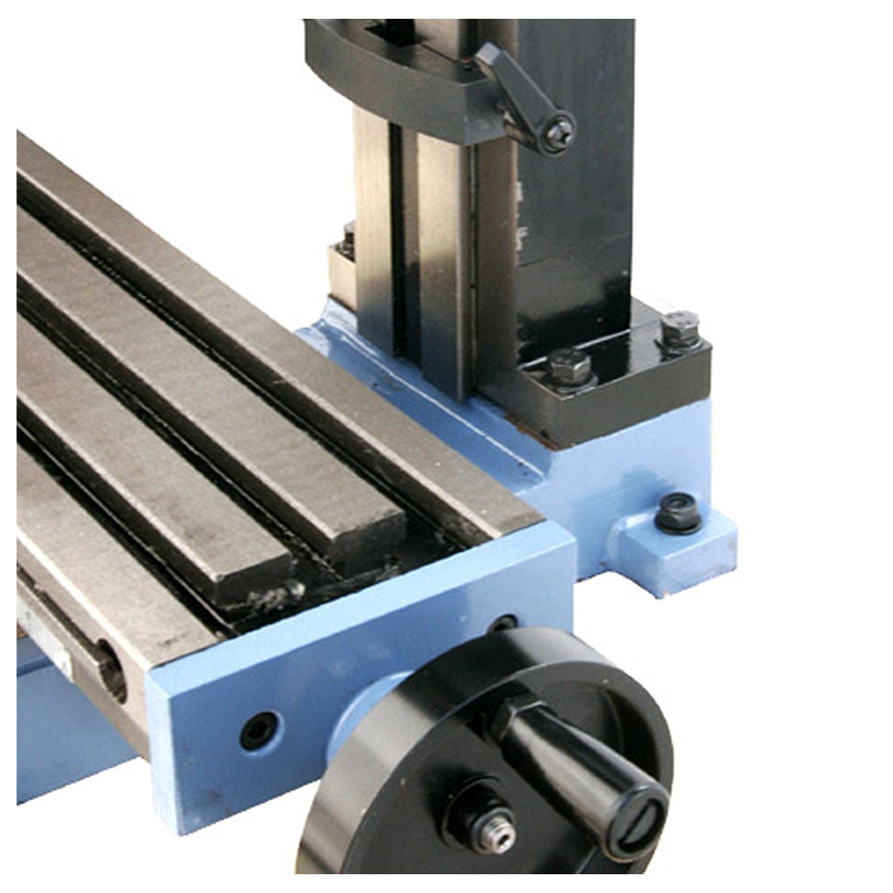
The machine vice is the workhorse. A precision milling vice bolts to the table’s T-slots and grips the work between a fixed and a moving jaw; most parts small enough for a mini mill are simply clamped in the vice, tapped down onto parallels so they sit flat and at a known height, and machined. The vice is fast, repeatable, and stiff, and a good one that is itself trammed square to the table’s travel is the foundation of accurate work. For the great majority of jobs on this machine, “put it in the vice” is the whole workholding plan.
Direct clamping to the table handles what the vice cannot — parts too large or awkwardly shaped to grip in jaws. Here the T-slots earn their keep: T-nuts drop into the 12 mm slots, and step clamps (with a stepped block to level them) bolt down over the edge of the work, pressing it against the table. The rules are the classic ones — clamp close to the cut, keep the clamp bolt near the work so the clamp bears down rather than levering up, and never let a clamp or bolt sit where the cutter will reach it.
The table’s T-slots themselves are the third element, the common interface everything else bolts to — vice, clamps, angle plate, rotary table, or a fixture the shop makes for a repeated job. Understanding that the T-slots are a standardised mounting grid, not just three grooves, is what lets a small mill hold an unexpectedly wide range of work.
4.3 Tooling: getting the cutter into the spindle
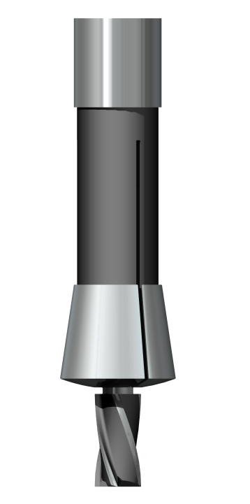
Between the R8 spindle and the cutter sits the tool-holding system, and on the 3990 that means R8 collets and their relatives. An R8 collet is a slotted, tapered sleeve that slides into the spindle’s R8 taper and is drawn up tight by the drawbar threaded down through the top of the spindle; as it seats, the slots close and the collet grips the tool’s shank. Each collet fits one shank size, so a set covers the common end-mill and drill-shank diameters. Collets are the preferred way to hold end mills, because they grip the shank concentrically and rigidly, close to the spindle nose.
Other tools reach the spindle through their own R8 holders: a drill chuck on an R8 arbor for twist drills, an R8 end-mill holder for tools with a flatted (Weldon) shank, an R8 boring head for boring. The common thread is the R8 taper and the drawbar — every tool change is loosen-drawbar, tap-out, swap, insert, tighten-drawbar. Because R8 is self-releasing, that tap to break the taper free is light.
End mills themselves come in types worth knowing: two-flute cutters clear chips well and are good for slotting and softer materials; four-flute cutters give a better finish and are stiffer for side milling; centre-cutting end mills can plunge straight down like a drill, while non-centre-cutting ones cannot. Choosing the right cutter for the job — and keeping it sharp — matters more on a low-powered mini mill than on a big machine, because a dull or wrong cutter is what a mini mill has the least power to overcome.
4.4 Speeds, feeds, and the discipline of a small machine
The 3990’s brushless drive gives a continuously variable 100–2500 rpm from a single dial, which removes the mechanics of speed changes but not the judgement. Spindle speed should suit the cutter diameter and the material — larger cutters and harder or gummier materials want lower rpm; small cutters and free-cutting materials want higher — and getting it roughly right is the difference between a clean chip and a burned edge or a squeal. Feed — how fast the work is pushed into the cutter — is by hand on this machine, and the goal is a steady rate that keeps each tooth cutting a real chip rather than rubbing (which work-hardens and dulls) or biting too hard (which chatters or breaks).
The discipline that a mini mill demands, and that a big mill forgives, is light depth of cut. The machine simply lacks the mass and power to hog metal, so material comes off in many shallow passes rather than a few deep ones — a few tenths of a millimetre at a time in steel, more in aluminium. The machine gives honest feedback: chatter, a labouring spindle, or a poor finish means back off the depth, the feed, or both. Worked this way the 3990 is capable and accurate; pushed like a Bridgeport it breaks cutters. Cutting fluid — flooded, brushed, or misted as the job allows — extends tool life and improves finish, especially in steel.
4.5 Climb versus conventional milling
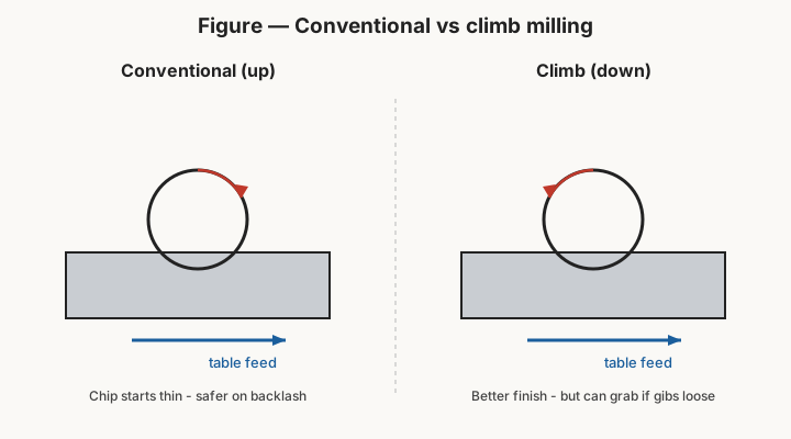
One choice comes up on nearly every cut and is worth understanding on a machine with backlash: the direction the cutter’s teeth move relative to the feed. In conventional (up) milling, the cutter rotates against the feed direction, so each tooth starts its cut at zero thickness and builds to full thickness. In climb (down) milling, the cutter rotates with the feed, so each tooth starts at full thickness and thins to zero.
The distinction matters on a mini mill because of backlash. In conventional milling the cutting force tends to oppose the feed and keep the leadscrew nut loaded against its screw, so the table is held steady even with some backlash present — it is the safer, more forgiving choice on a machine with loose-ish screws. In climb milling the cutting force acts in the same direction as the feed and can try to pull the table into the cut, snatching up the backlash suddenly; on a light machine with backlash that can grab, gouge the work, or break the cutter. Climb milling gives a better finish and lower tool wear when the machine can control it, so it is used deliberately — with tight gibs, minimised backlash, and light cuts — while conventional milling is the default, especially for roughing. Knowing which is which, and choosing on purpose, is a mark of understanding the machine.
4.6 Tuning: gibs and backlash
A mini mill is a machine the owner keeps in tune, and two adjustments come up most: the gibs and the backlash.
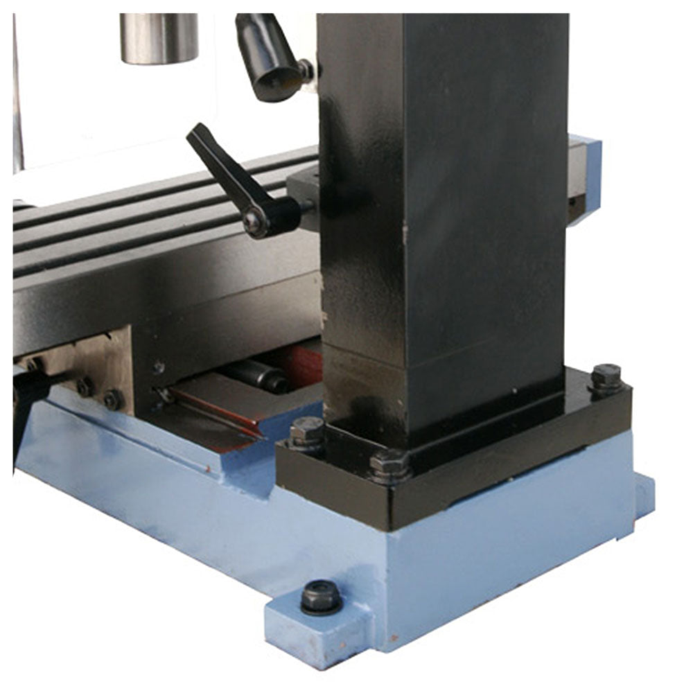
The gibs are the tapered strips that take up clearance in each dovetail slide (X, Y, and Z). Set too loose, the slide has play — the table or head can rock, and cuts chatter and lose accuracy. Set too tight, the slide binds, the handwheel is stiff, and the ways wear. The gib on each axis is adjusted with its screws until the slide moves smoothly with a slight, even drag and no detectable play — a feel that is learned, and that is re-checked as the ways wear in. The Z gib in particular is set with a little more drag so the head holds position under the weight it carries (helped by the air spring).
Backlash is the lost motion in each leadscrew, and while the DRO makes it nearly irrelevant for positioning (the scales read true regardless), it still matters for cutting — it is what makes climb milling risky and what can let a cut pull the table. Backlash on a mini mill can be reduced by adjusting or replacing the leadscrew nuts (some builders fit anti-backlash nuts), and it is measured periodically so the operator knows how much is present. The important mental shift the DRO brings is this: you no longer compensate for backlash to find a position — the readout does that for you — but you still respect it when choosing cut direction.
4.7 How the DRO changes the workflow
With the TouchDRO system fitted (Volume 3), the day-to-day use of the machine changes in concrete ways, and every operation above is set up differently than it would be on a bare mini mill.
Setting a datum replaces counting turns. The work is clamped, an edge or a corner is picked up (touching the cutter or an edge finder to a known feature), and that point is zeroed on the readout. From then on every position is an absolute coordinate from that datum — “the hole is at X 25.00, Y 12.50” — dialled in by watching the numbers, not by remembering handwheel turns.
Backlash stops being a calculation. Because the scales read the table’s real position, the operator no longer winds out backlash or approaches every dimension from one side to be safe; the number is true the instant the table moves. This alone removes a whole category of error and a great deal of mental load.
Hole patterns become trivial. A bolt circle that would otherwise demand trig and careful dial work is entered into the app — centre, diameter, number of holes — and the readout walks the operator to each hole in turn, saying “go here” for each one. Rows of holes, pockets located by coordinate, and parts zeroed on their own features are all a few taps.
Precision creeps become confident. Boring to a diameter, milling to a shoulder, facing to a thickness — each becomes a matter of watching a live coordinate approach its target, so the operator can sneak up on a dimension in known increments and stop exactly on it rather than measuring, guessing the next cut, and measuring again.
The net effect is that the 3990 stays a fully manual machine — the hands still turn every handwheel, the operator still owns every cut — but the readout removes the arithmetic, the backlash guesswork, and the pattern math, leaving attention free for the thing that actually makes good parts: watching and feeling the cut. That combination, a capable brushless solid-column mini mill plus an honest absolute readout, is what makes this machine the shop’s first reach for manual work.
4.8 A word on safety and habit
None of the above is safe if the basics are neglected, and a mini mill deserves the same respect as any machine that spins a sharp tool. Eye protection is worn at the machine, always. Sleeves, gloves, and anything that can be caught by a rotating spindle are kept well clear — gloves in particular are never worn while cutting, because a glove that catches a cutter takes the hand with it. The drawbar is checked tight before every spindle start; a tool that spins loose in the taper is dangerous and ruins the taper. Chips are cleared with a brush, never fingers, and never while the spindle turns. The work and every clamp are confirmed solid before power is applied, and the operator keeps a hand near the stop.
Good habits compound with the DRO rather than being replaced by it: zero a clean datum, dial the head down so the quill is short, take the trial cut light, read the number, and only then commit. Those routines — unglamorous, repeated every setup — are what let a small manual mill produce work that punches well above its 56 kilograms, session after session, without drama.
Comments (0)