HiTorque 7×16 Mini Lathe · Volume 2
The Machine in Detail — Anatomy, Drive, and the Deluxe Refinements
2.1 Reading the machine
To use a lathe well, an operator has to be able to name its parts and know what each one constrains. Every cut is the sum of a spinning axis and a tool moved in two directions relative to it, and every part of the machine exists to define one of those things rigidly and repeatably. What follows walks the HiTorque 7×16 (LMS 7450 / SC20) from headstock to tailstock, describes the brushless drive and its electronic speed control, explains the lead screw and change gears that make it a screw-cutting lathe, and closes with the “Deluxe” refinements and the range of materials the machine will handle. Where a number is given it is LittleMachineShop’s published figure for this model.
2.2 The bed and ways
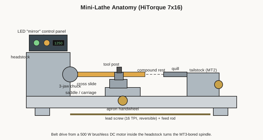
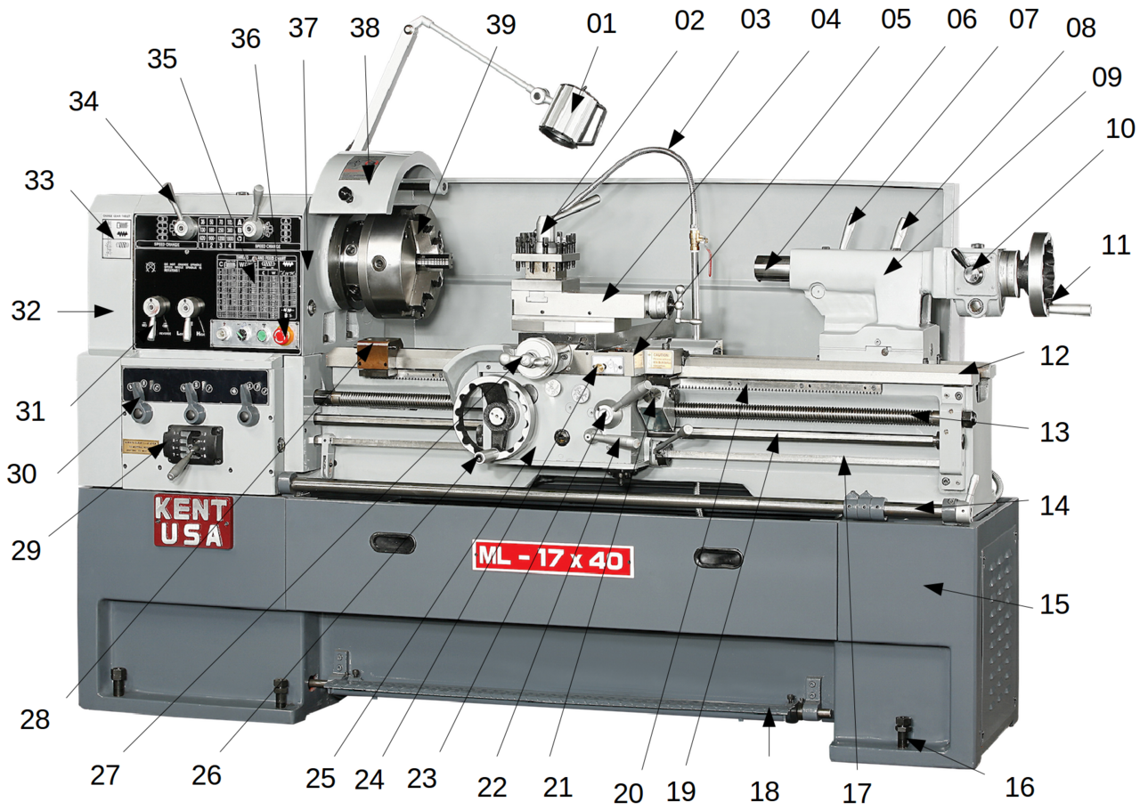
Everything on the lathe is located by the bed — a heavy cast-iron beam that runs the length of the machine and carries, on its top, the precision-machined ways: the flat and vee surfaces along which the carriage and tailstock slide. The bed’s job is to hold the spindle axis and the tool’s path parallel to each other along the whole length of a cut. If the ways are not straight, or if the carriage is not properly fitted to them, a part that should be a cylinder comes out a taper. On a 7×16 the bed is the long version of the family casting, giving the roughly 16.14 in (410 mm) of distance between centers that names the machine, and it is the single feature that most distinguishes this machine from the shorter 7×12 and 7×14 lathes.
Because the bed is the reference for everything, its condition and cleanliness matter more than any other single thing. Chips must be brushed off rather than dragged along, the ways must be kept oiled, and (as covered in the tuning volume) the machine must sit without twist, because a bed twisted by an uneven bench will cut a taper no matter how carefully the operator works.
2.3 The headstock and spindle
At the left end of the bed stands the headstock, a rigid casting that houses the spindle — the rotating shaft that grips and turns the work. The spindle is the heart of the machine, and its specifications set much of what the lathe can and cannot do.
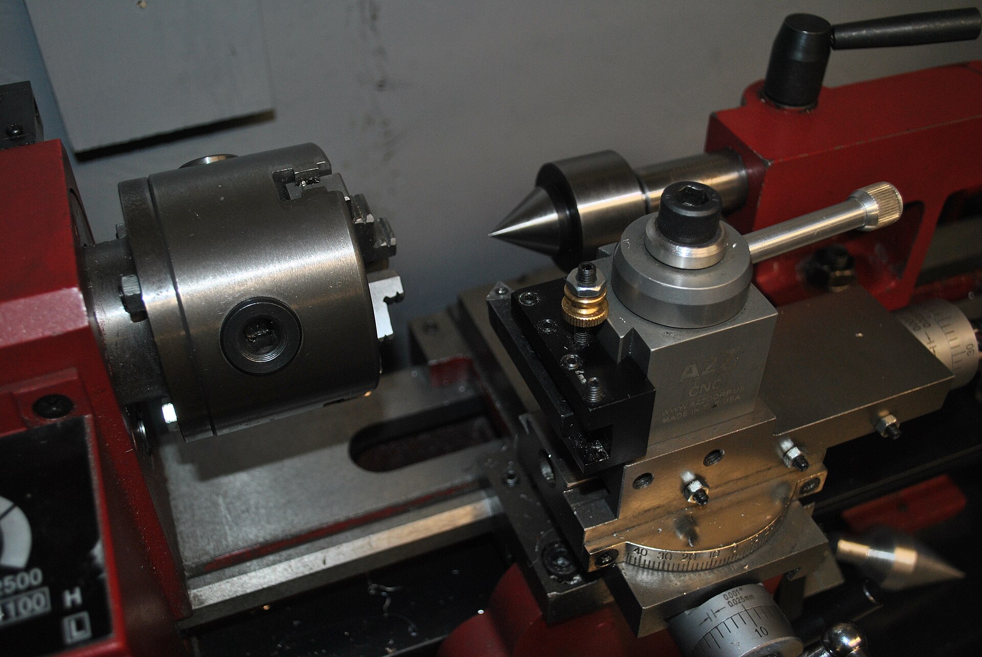
On this machine the spindle runs in quality NSK (Japanese) bearings for smooth, quiet rotation, and it is bored through with a 0.787 in (20 mm) hole. That through-bore is more useful than its modest size suggests: it lets bar stock pass through the headstock so that long material can be fed forward as work is parted off, rather than hanging out the back or being cut to short lengths first. The nose of the spindle carries an MT3 (No. 3 Morse taper) internal taper, which accepts Morse-taper accessories — a live or dead center, a Morse-taper drill chuck, or collet fittings — directly into the spindle, and the external nose is threaded and registered to carry the chuck. The Morse taper is a self-holding taper: an accessory pushed into it seats on friction and runs true, and is knocked out with a drift through the bore when finished.
The chuck that mounts on the spindle nose is what actually holds the work; that, and the other things that go on the spindle and in the tailstock, are the subject of the tooling volume. What matters here is that the spindle defines the axis of every cut, and its bore, taper, and bearing quality set the limits of the work the lathe can hold and how truly it will run.
The way the chuck attaches to the nose is worth understanding, because it governs how accurately work runs and how easily accessories interchange. On these machines the chuck (or a faceplate) mounts to a register on the spindle nose — a precisely-machined shoulder and pilot diameter that locate the accessory concentric with the spindle axis — and is secured with studs or bolts, often through an intermediate backplate turned to fit both the chuck and the nose. Because everything registers to the same spindle nose, a three-jaw chuck, a four-jaw chuck, a faceplate, or a collet closer can each be swapped onto the spindle and each will run true to the machine’s axis; the accuracy of a given setup then depends on the accessory itself and on how carefully it was mounted, not on the spindle, which is the fixed reference the whole machine is built around.
2.4 The carriage, cross-slide, and compound
Riding the ways between headstock and tailstock is the carriage — the assembly that carries the cutting tool and moves it along and across the work. It is built up in layers, and understanding the stack is the key to understanding how a cut is controlled.
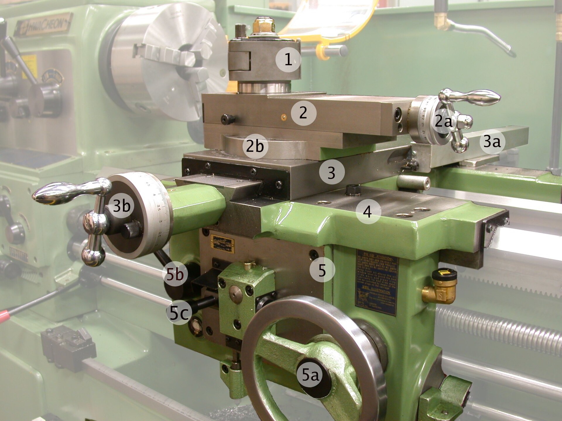
The bottom layer is the saddle, the H-shaped casting that spans the bed and slides along it, providing motion parallel to the spindle axis — the Z direction in lathe terms, the direction that sets a cut’s length and turns a diameter down its length. Hanging from the front of the saddle is the apron, which carries the controls that drive the carriage: the large hand-wheel for moving it by hand, and the half-nuts that clamp onto the lead screw to drive it by power for feeding and thread cutting.
On top of the saddle sits the cross-slide, which moves perpendicular to the spindle axis — the X direction, in and out, setting the depth of a cut and doing the across-the-face motion of facing. Its travel on this machine is 2.559 in (65 mm), and it carries a 40-division graduated dial (plus, on this Deluxe model, a DRO scale) so the operator can advance it by a known amount. The swing over the cross-slide — the largest diameter that clears the top of the slide — is 2.165 in (55 mm).
On top of the cross-slide sits the compound rest (or “top slide”), a small slide that can be swiveled to any angle and carries the tool post at its top. The compound’s job is to feed the tool at an angle — most importantly for cutting short tapers and for the angled infeed used in thread cutting — and to make small, controlled advances. The tool post itself, which clamps the cutting tool at center height, is where the Deluxe model’s quick-change unit lives; it is covered in the tooling volume.
The whole point of this stack — saddle for Z, cross-slide for X, compound for angled feed — is that it turns the operator’s two hands on two graduated hand-wheels into a precisely controlled tool path in a plane. Every turned, faced, bored, or threaded surface is produced by some combination of those motions, made either by hand or, for the along-the-bed motion, driven automatically by the lead screw.
2.5 The tailstock
At the right end of the bed sits the tailstock, which slides along the ways and clamps down wherever it is needed. It carries a quill — a barrel that advances and retracts on a hand-wheel — bored with a No. 2 Morse taper (MT2). The tailstock does two main jobs. First, it supports the free end of a long workpiece with a center (live or dead) held in the quill, so that a slender part does not flex away from the tool or whip. Second, it acts as a drilling and reaming station: a Morse-taper drill chuck (or a large taper-shank drill) goes into the quill, and the work spins while the operator feeds the tool straight into its face by winding the quill forward, drilling exactly on the axis. The machine ships with an MT2 dead center for the tailstock.
Because so much depends on the tailstock’s alignment with the spindle axis, it is designed to be adjustable side to side, and getting that alignment right is one of the standard tuning tasks covered later. A tailstock even slightly off the centerline will drill crooked holes and turn unintended tapers when it is supporting work.
2.6 The brushless drive and electronic speed control
Inside the headstock, the spindle is turned by a 500-watt brushless DC (BLDC) spindle-drive motor through a belt — and, as emphasized in the overview, there are no gears in the spindle drive at all. A single belt runs from the motor pulley directly to the spindle, and the motor’s electronic controller does all the rest.
This is what gives the machine its continuous 100–2500 RPM speed range, adjustable while running by the variable-speed knob and available in both directions. Where an older brushed-and-geared machine offered two mechanically-selected bands and made the operator open the headstock to move between the low and high ranges, here the speed is simply dialed in and read back on the integrated tachometer. More important than convenience is the torque behavior: a brushless motor under electronic control can maintain useful torque well down toward the bottom of its range, so heavy cuts, large-diameter facing, and threading up to a shoulder at low RPM do not stall the spindle the way they could on the older design. The controller also manages acceleration and braking, so the spindle comes up to and down from speed in a controlled way rather than lurching.
Practically, the drive removes two recurring headaches of the classic mini lathe: the gear change (gone entirely) and the brushes and their associated control-board failures (gone with the brushed motor). What remains is a quiet, torquey, electronically-governed spindle that is genuinely pleasant to run — the single feature most responsible for the HiTorque line’s reputation.
2.7 The lead screw and change gears
A lathe becomes a screw-cutting lathe when the carriage can be driven along the bed in a fixed, selectable ratio to spindle rotation. That is the job of the lead screw and the change gears, and it is what lets the machine cut threads and take a smooth powered feed.
The 7×16 has a reversible 16-TPI lead screw running along the front of the bed. When the operator closes the apron’s half-nuts onto it, the turning lead screw drives the carriage along at a rate fixed by the gearing between the spindle and the lead screw. Change that gearing — by swapping gears in the supplied 11-gear change-gear set — and you change how far the carriage advances per spindle revolution, which is exactly the pitch of a thread. This machine’s published threading capability is 4 to 80 threads per inch (TPI) for imperial threads and 0.3 to 8.0 mm pitch for metric, with a dedicated 21-tooth gear included to enable the metric ratios. The machine uses real top and bottom half-nuts, a more robust arrangement than the single-nut feed of some budget machines.
The same lead-screw drive, at a fine ratio, provides a power longitudinal feed for ordinary turning — a slow, perfectly even carriage motion that produces a far better surface finish than hand-feeding can, and that spares the operator’s hands on long cuts. Setting up the change gears for a given thread, and using the thread dial to keep successive passes in the same groove, is the subject of the operations volume; what matters structurally is that the lead screw and change gears are the mechanism that ties tool motion rigidly to spindle rotation.
2.8 The “Deluxe” refinements
Everything above is common to the HiTorque 7×16 family. What distinguishes the 7450 Deluxe — the machine documented here — is a set of refinements layered on that common core, each aimed at making the machine faster to set up and easier to work to a number.
The most visible is the LED “mirror” control panel across the front of the headstock: a dark glass fascia carrying illuminated, clearly-organized controls — start/stop, spindle direction, an emergency-stop switch, the variable-speed knob, and an integrated digital tachometer reading actual RPM. The second is the factory two-axis DRO: magnetic scales on the longitudinal and cross feeds report position over Bluetooth to a tablet display, with additional digital readouts on the compound rest and tailstock and a 40-division dial on the cross slide. The third is the workholding and control hardware: a 0XA wedge-type quick-change tool post with five holders, aluminum hand-wheels and chrome levers that are larger and better to use than plain plastic knobs, and the quality NSK spindle bearings noted earlier. The machine weighs about 108 lb (49 kg) and runs on 120 V, 60 Hz, 8 A.
None of these change what the machine fundamentally is, but together they change how it feels to use: the controls are where the hand expects them and lit; the DRO removes most of the mental arithmetic and backlash-counting of working to a dial; and the quick-change tool post makes swapping between a turning tool, a parting blade, and a boring bar a few-second operation rather than a re-shimming exercise.
2.9 Materials it handles
Within its size and rigidity, the 7×16 is a genuine metal lathe, not a soft-materials toy, and the brushless torque widens the range of what it will cut comfortably. Aluminum and brass are its easiest and most pleasant materials, turning cleanly at higher speeds with excellent finishes. Mild and free-machining steels are well within its capability for the modest depths of cut a machine this size takes; the low-end torque is exactly what makes steel practical, since steel wants lower speeds and more force than aluminum. Cast iron, bronze, and most engineering plastics (Delrin/acetal, nylon, PTFE, PVC, acrylic) all machine well, with the usual cautions about dust and heat for plastics. Harder and tougher materials — stainless steels, tool steels, titanium — can be turned in light cuts with sharp tooling and patience, but they push against the limits of the machine’s rigidity and are where the operator most has to respect small depths of cut and appropriate speeds.
The governing constraint is not the motor but the machine’s mass and stiffness: a bench lathe cannot take the deep, heavy cuts a floor-standing engine lathe can, so material is removed in more, lighter passes. Understood that way, the 7×16 handles the full range of materials a model shop routinely works, and the brushless drive means it does so with torque to spare where the older machines ran out of it.
Comments (0)