Pcb Soldering Jig · Volume 1
A Flip-Over Jig for Soldering Through-Hole Boards
1.1 The Job
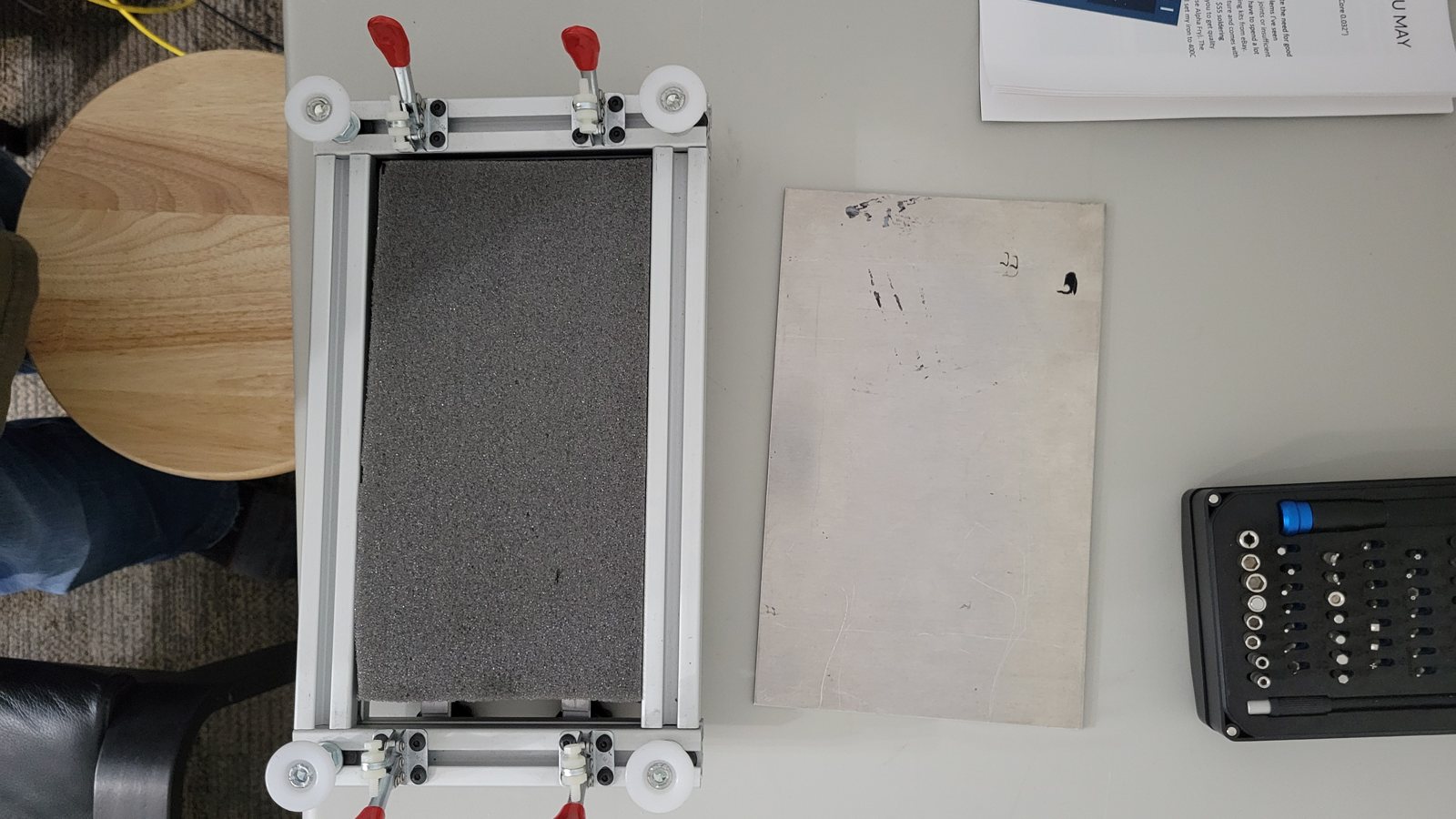
Every through-hole kit runs into the same problem. A part goes into its holes from the component side, but it is soldered from the other side, so the board has to be turned over with the part still in it. A resistor with its leads bent out stays put. A chip socket, a pin header, an LED or a key switch does not: it drops out, or sits crooked, or lifts a millimetre off the board while the first pin is soldered, and that pin then holds it there. The usual fixes are a finger, a blob of Blu Tack, a strip of masking tape, or soldering one pin, reheating it and pushing the part down. All of them work for one part at a time, and none of them works for a row of fifteen key switches.
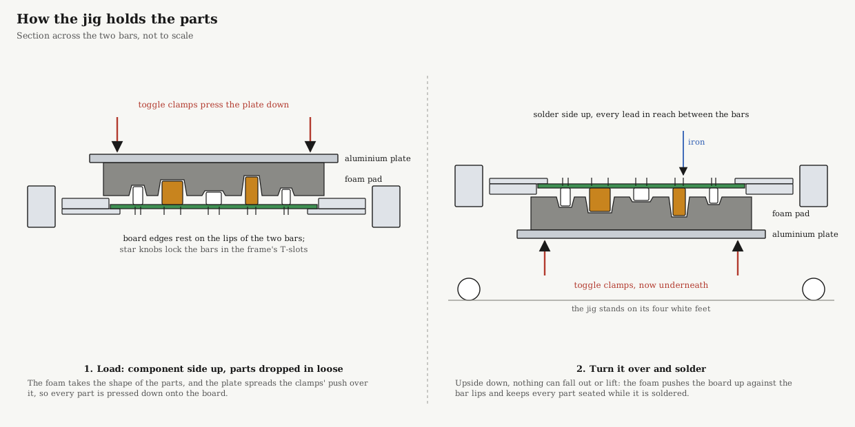
My jig, built to a design published in Nuts and Volts, solves it for a whole board at once. The board is held by its edges, every part is dropped into its holes, a foam pad and a plate are clamped down over the parts, and the whole thing is turned over. Every part is now pressed flat against the board, and every lead is facing up.
1.2 The Design
The design is John D. Collier’s “Build A Circuit Board Assembly Jig”, Nuts and Volts, September 2011 (nutsvolts.com). Collier wanted a board holder that stayed still, left room for the iron, and could hold through-hole parts in place upside down, after finding a third-hand gripper too flimsy and ready-made board jaws too deep or the wrong size. He based it loosely on the professional rework fixtures that hold parts down with soft foam.
In outline it is a frame of 1 in 80/20 T-slot extrusion, two notched aluminium board rails held by knobs, a 1 in polyurethane foam pad on a ⅛ in aluminium compression plate, four toggle clamps and four levelling feet: about $80 of parts in 2011, mostly from McMaster-Carr. Two small side supports let it stand on edge for parts that must be reached from both sides at once. Volume 2 is the full build, with his drawings and cut list.
1.3 How It Works
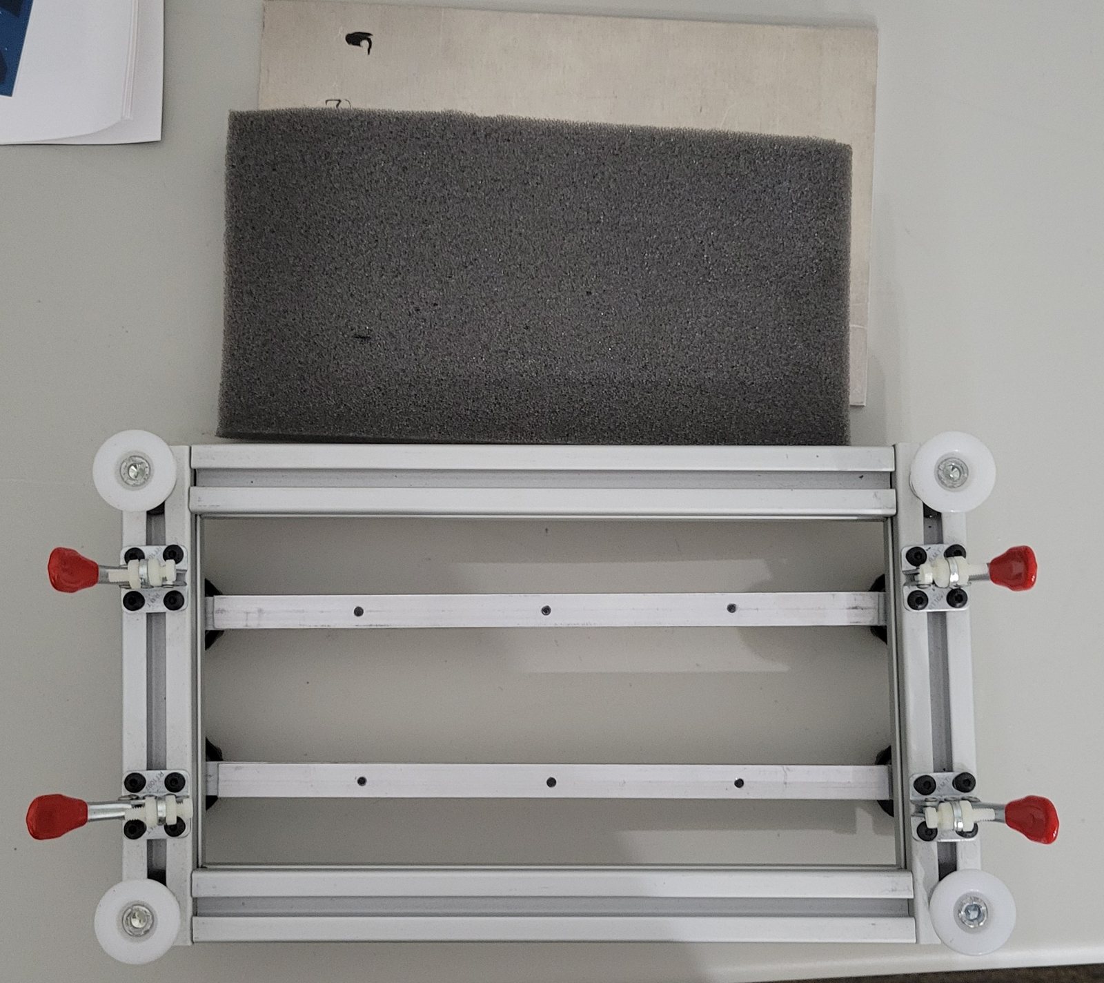
The jig has four parts.
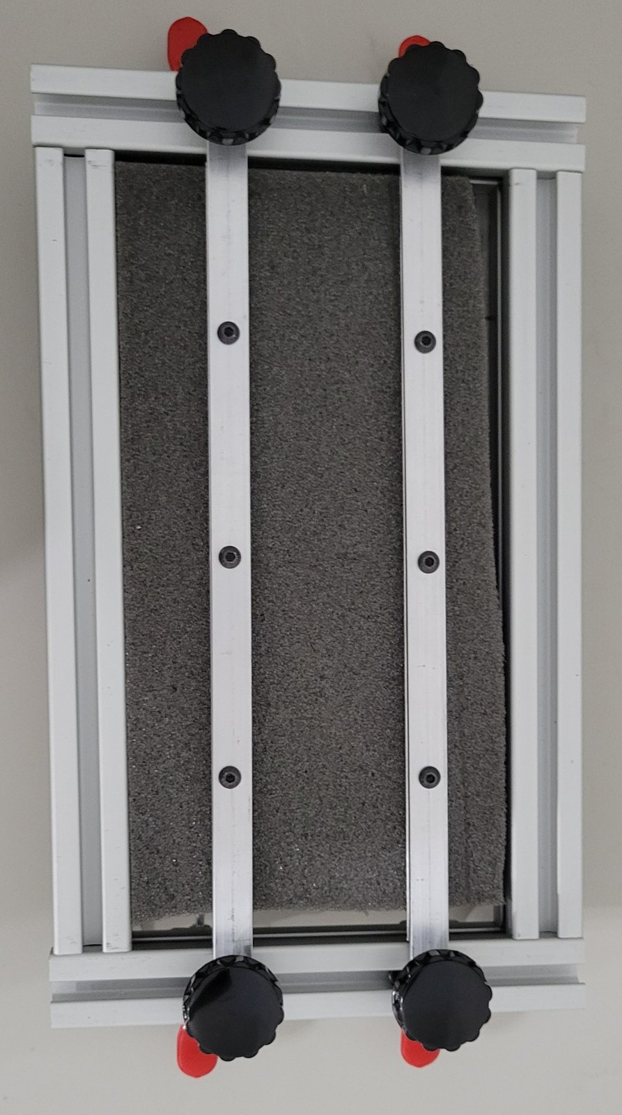
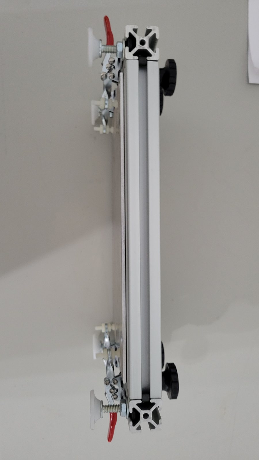
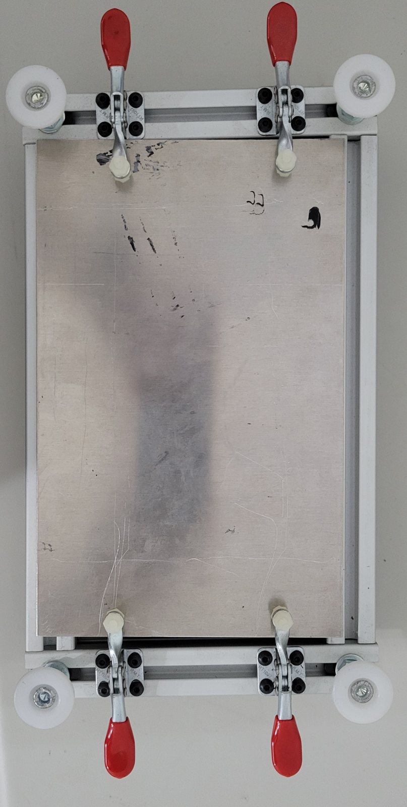
- A frame of aluminium T-slot extrusion, a little larger than the biggest board it will take. It has two faces: one carries the four toggle clamps and four levelling feet with white nylon pads, the other the star knobs of the board bars.
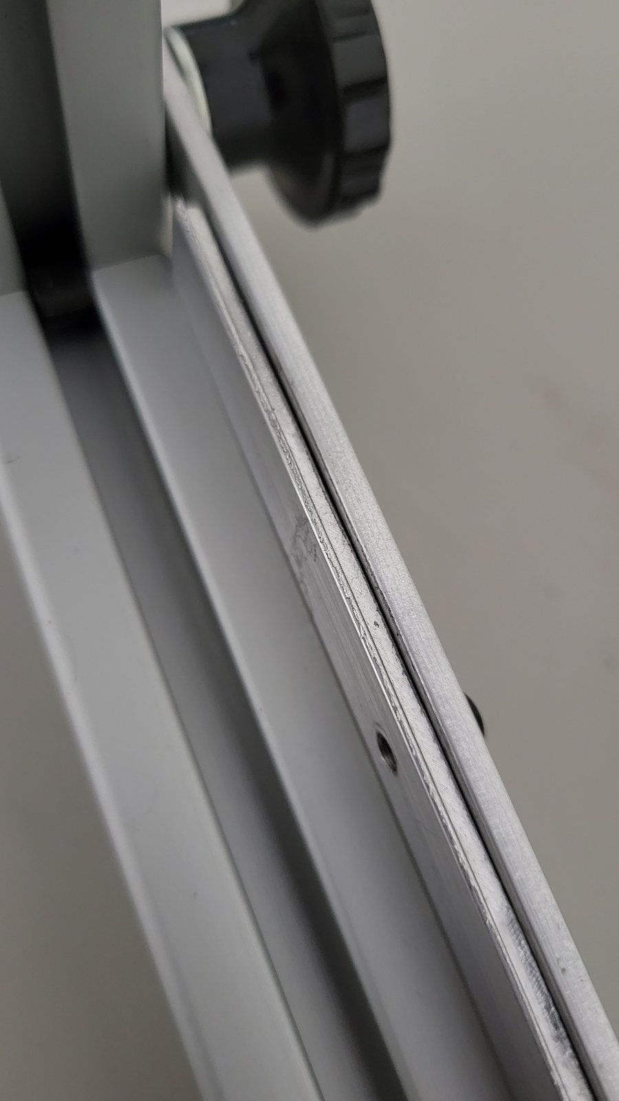
- Two board bars that run the length of the frame. Each is an aluminium bar built up from two flat strips held together by three countersunk screws, one strip set back from the other so that the bar has a narrow lip along its inside edge. A star knob at each end clamps the bar to the frame, on a T-nut in the frame’s slot, so a bar can be loosened, slid across to the width of the board, and locked again.
- A foam pad that passes through the frame’s opening and lies over the parts.
- An aluminium plate that goes on top of the foam, and four toggle clamps (the kind used to hold work down on a machine table, each with a lever and a threaded spindle with a nylon tip) mounted on the frame’s two ends, two at each end, which hold the plate down. The plate is wider than the frame’s opening, so it comes down onto the frame’s two long sides and stops there.
1.4 Using It
The sequence is the same for every board.
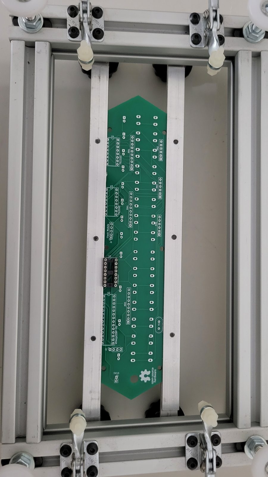
- Set the bars. With the knob side down, slacken the four knobs, lay the board on the lips with its component side up, slide the bars in until they hold its two long edges, and tighten the knobs.
- Load the parts. Drop every part into its holes. Nothing needs bending or taping; the parts only have to stand in their holes until the foam goes on.
- Foam, plate, clamps. Lay the foam pad over the parts, put the plate on the foam, and swing the four toggle clamps over. The foam squashes round the parts and each part is pressed down onto the board. Because the plate stops on the frame, how hard the foam squeezes is set by the depth of the frame and the height of the parts, not by how hard the clamps are pulled: the clamps only have to keep the plate on the frame.
- Turn it over. The jig now stands on its four white feet with the solder side up, and every lead sticks up between the bars. The lips take the push of the foam from below, so the board cannot lift.
- Solder, then trim. Solder every joint, clip the leads, turn the jig back over, release the clamps, and lift the plate and foam off.
A board with parts on both faces, like the µKENBAK-1 below (chips on the back, switches and lamps on the front), simply goes through twice, once each way up.
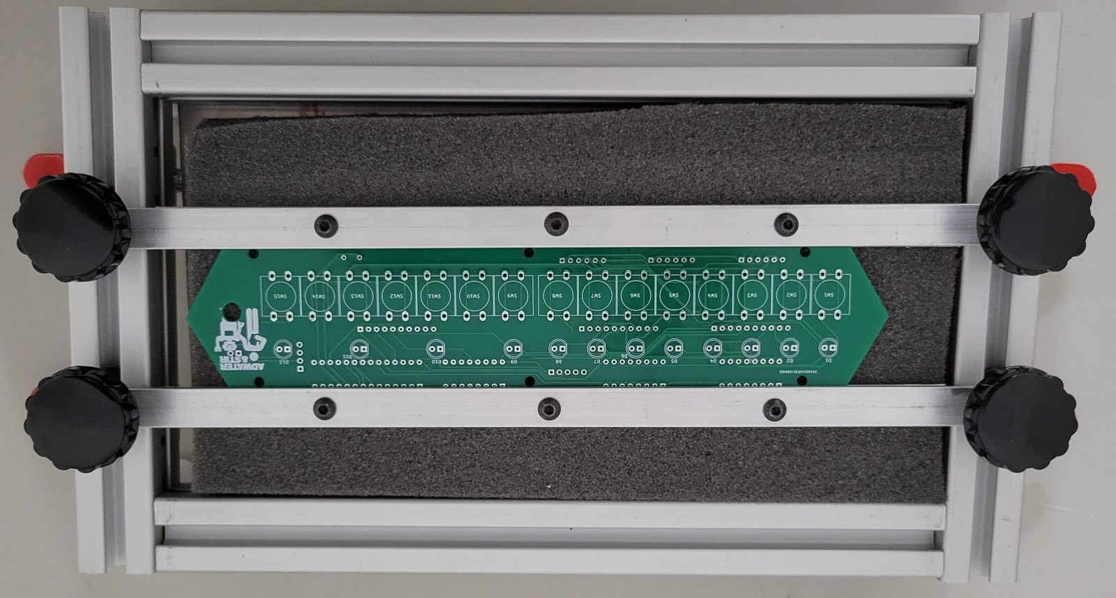
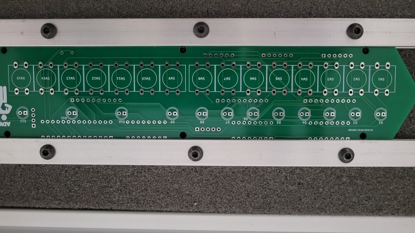
1.5 Getting Good Results
Low parts first. Collier’s own advice is to populate the board smallest to tallest. One foam pad presses hardest on the tallest part under it. If a 2 mm resistor sits next to a 12 mm electrolytic capacitor, the foam bottoms out on the capacitor and barely touches the resistor. The cure is the standard kit-builder’s order: load and solder the lowest parts first (resistors and diodes, then chip sockets, then headers and transistors, then the tall capacitors, switches and connectors), so each pass has parts of about the same height. A pad that is thick and soft enough to wrap round a mix of heights helps too. For parts too tall or awkward for the foam, Collier holds them with a dab of non-conductive superglue or by bending a lead slightly, or solders one hole first and melts that plug of solder while pushing the part in. He also lays the board with its long side along the rails, for strength.
One edge at a time is enough. Before soldering a whole row of a multi-pin part such as a chip socket or a header, solder one pin at each end and look at the part from the side. If it is flat, finish the row. If it is not, one joint reheats and the part can be pushed down; with every pin soldered, it cannot.
Static. Ordinary polyurethane foam is an insulator and can build up a charge. That does not matter for resistors, sockets and switches, but loaded chips (rather than empty sockets) are better pressed with conductive foam, the black or pink kind that chips are shipped in, or kept off the board until it is finished and plugged into their sockets afterwards.
Heat. The foam is on the component side and the iron is on the other, with the board between them. Collier reports that soldering heat had not melted his polyurethane foam.
1.6 My Build
I built this jig myself to Collier’s design; it is not a kit. The first board in these photos is my µKENBAK-1, the half-scale KENBAK-1 kit from Adwater & Stir, whose front board carries a row of fifteen key switches and twelve lamps that all have to sit flat and square behind the front panel. The kit itself is covered in KENBAK-1, Volume 13: My µKENBAK-1.
As the photos show, mine follows the article closely, levelling feet and all. The differences are small: each toggle clamp sits on a little square adapter plate held by four cap screws rather than being screwed straight into the extrusion, my foam pad lifts out loose instead of being glued to the plate, and I have not fitted the side supports. I made the board bars with Collier’s no-mill alternate, two thin strips screwed together with one offset from the other, rather than milling a notch. I work with standard 1.6 mm boards, kit boards included, and the lips are sized for them. The star knobs, ¼-20, came either from the box of ¼-20 hardware I keep or from eBay; I no longer remember which. Any ¼-20 star knob with a stud, or on a short length of threaded rod, does the job. Volume 2 covers the build itself.
Sources
- The design: John D. Collier, “Build A Circuit Board Assembly Jig”, Nuts and Volts, September 2011, nutsvolts.com/magazine/article/september2011_Collier.
- The jig and the µKENBAK-1 board: my photos, 7 November 2026.
- The µKENBAK-1 kit: KENBAK-1, Volume 13, iconic-machines.fubsypoly.com.
Next — Volume 2: Building It. Collier’s drawings, the cut list, the board rails with their 0.060 in notch, the clamps, feet, foam and plate, step by step, with the parts list as a printable BOM.
Comments (0)