Pcb Soldering Jig · Volume 2
Building It
2.1 What Gets Built
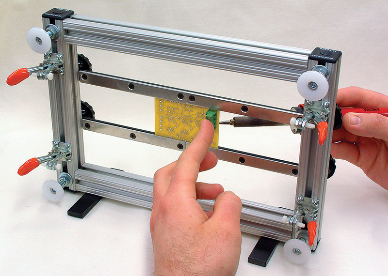
This is the jig of Volume 1 as John D. Collier drew it in Nuts and Volts in September 2011 (nutsvolts.com), built the way I built mine. Every dimension below is from his drawings. Where my jig differs, the text says so.
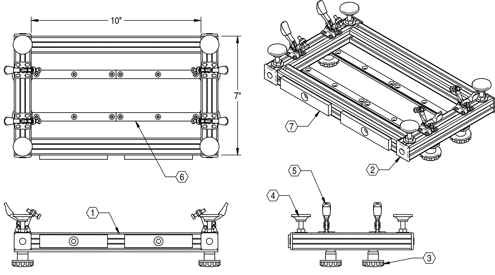
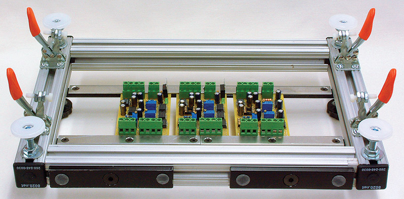
The finished jig is a frame 12 in long and 7 in wide over its extrusions, 1 in deep, with the board rails across its top face and the clamps and feet on its bottom face. Collier does not give a maximum board size. The foam pad, 5 × 9¾ in, sets a practical limit of about that size, and he notes that the long side of the board should lie along the rails “for maximum strength”. His own use was several small boards side by side (Figure 7).
The tools are modest: a saw that cuts aluminium square (he suggests a power mitre saw), a drill press, a ¼-20 tap and an 8-32 tap, a countersink, and for the board rails either a milling machine or the no-mill alternative described below.
2.2 Parts
Table 1 — Parts
| # | Part | Qty | Collier’s source (2011) |
|---|---|---|---|
| 1 | 80/20 #1010 T-slot extrusion, 1 × 1 in | 2 ft stock, 2 pieces | McMaster-Carr 47065T209 |
| 2 | T-nut, ¼-20, 80/20 #3382 | 10 | McMaster-Carr 47065T142 (4 per pack) |
| 3 | Extrusion connector (anchor fastener), 80/20 #3381 | 4 | McMaster-Carr 47065T155 |
| 4 | End cap, 80/20 #2015 (optional) | 4 | McMaster-Carr 47065T91 |
| 5 | Knob with ¼-20 threaded stud | 4 | McMaster-Carr 6479K88 |
| 6 | Levelling mount | 4 | McMaster-Carr 23015T82 (12 per pack) |
| 7 | Horizontal toggle clamp | 4 | Fargoware FC-20, De-Sta-Co 205-S or Carr-Lane CL-150-HTC; MSC 76988120 |
| 8 | Board support rail (made) | 2 | ⅛ × ½ in aluminium bar; #6-32 flat-head screws |
| 9 | Side support (made, optional) | 2 | ¼ × ¾ in aluminium bar; ¼-20 flat-head screws |
| 10 | Foam compression plate (made) | 1 | ⅛ in aluminium sheet |
| 11 | Foam | 1 | 1 in polyurethane foam, craft shop; 3M Super 77 spray adhesive |
The ten T-nuts are four for the rail knobs on the top face, four for the feet on the bottom face, and two for the side supports on the front. Part numbers are as Collier listed them in 2011; check them before ordering. The same list, with tick boxes and alternates, is the printable BOM at the end of this volume.
2.3 The Frame
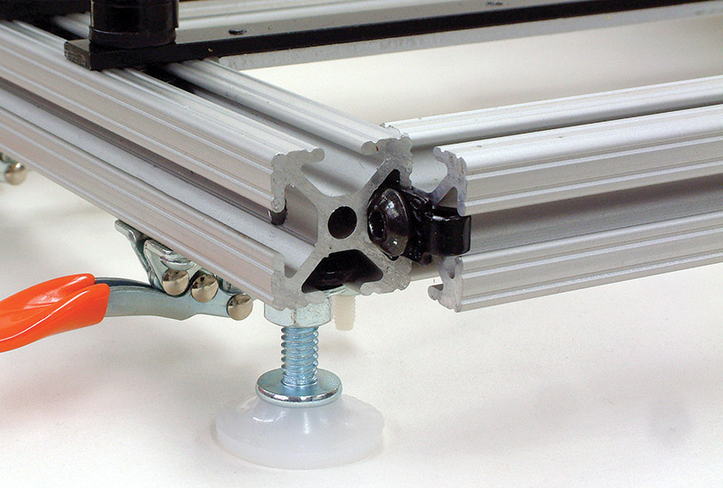
The frame is four pieces of 1010 cut from two 2 ft lengths: two long sides of 10 in and two end pieces of 7 in, so each 24 in length gives one of each with room for the saw. The 10 in dimension in Figure 2 is the distance between the end pieces, and the end pieces run the full 7 in width.
- Cut all four pieces square. Any error in squareness shows up later as a frame that rocks.
- Tap both ends of each 10 in piece ¼-20, into the extrusion’s centre hole, for the connectors.
- Drill each 7 in end piece with a ¼ in access hole ½ in from each end, on the line of the 10 in pieces’ centres, so a 5/32 in hex key can reach the connector.
- Load the T-nuts before assembling, because a closed frame will not take them: four in the top face (rail knobs), four in the bottom face (feet), two in the front face (side supports).
- Assemble with the four connectors on a flat surface, and tighten them through the access holes.
2.4 The Board Rails
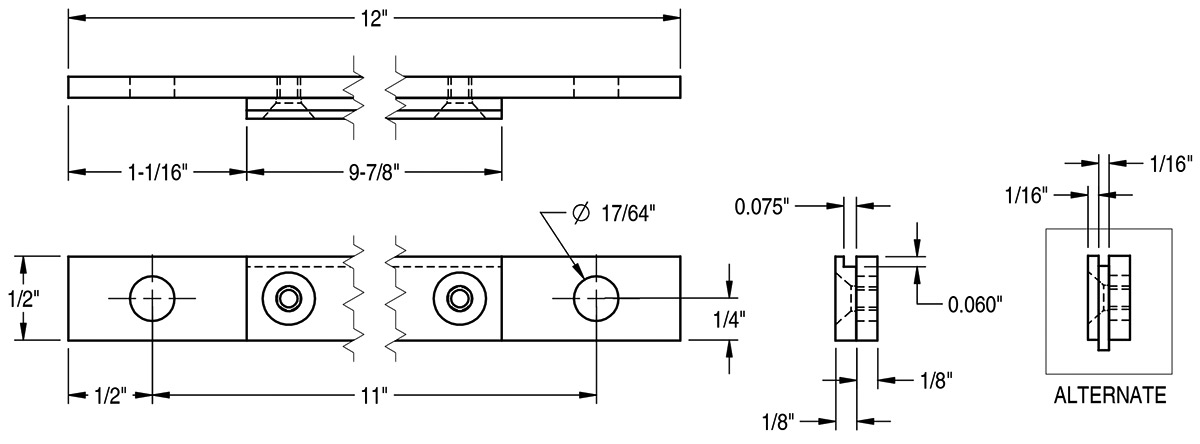
The rails are the one part that needs care. Each is two layers of ⅛ × ½ in aluminium: a plain bar 12 in long, which rides on the frame and takes the knobs, and under it a notched section 9⅞ in long, which hangs into the frame’s opening between the end pieces. The notch, 0.075 in by 0.060 in along the inner edge, is the ledge that the board’s edge sits on. Its width depends on the boards. A standard board is 1/16 in (0.063 in) thick, and Collier made the notch “as shallow as possible”. His notched section ended up as two identical pieces butted end to end.
- Cut the two 12 in bars and the notched sections.
- Mill the notch along one edge of each notched section.
- Clamp each notched section to its bar and drill the pilot holes through both. Collier used six screws per rail and says four would do.
- Countersink the holes in the notched section and tap the bar #6-32, so the flat-head screws sit flush in the notched section’s exposed face.
- Drill the 17/64 in knob holes ½ in from each end of the bar.
Without a mill, the alternate does the same job with two 1/16 × ½ in strips set 1/16 in apart across their width, so the edge of one stands proud of the other as the ledge. That is how I made mine: two strips with a step between them, held by three countersunk screws (Volume 1, Figure 5). For standard 1.6 mm boards, which is what I use, the 1/16 in step is the right depth.
The knobs Collier specified have studs long enough to bottom in the T-slot before they tighten. He adds a few washers under each knob, or cuts about ⅛ in off each stud.
2.5 Clamps, Feet and Side Supports
The feet thread into the four T-nuts on the bottom face. A nut and washer on each stud, run down before the stud goes into its T-nut, lets each foot be set to a height and locked, so the jig sits level and does not rock.
The toggle clamps’ mounting holes do not line up with the T-slot. Collier positions each one on the bottom face of an end piece, marks its holes, then drills and taps them part-way into the extrusion, #8-32. On mine, each clamp is screwed to a small square adapter plate, and the plate is held by four cap screws (Volume 1, Figure 3), which spares the extrusion and leaves the clamps adjustable.
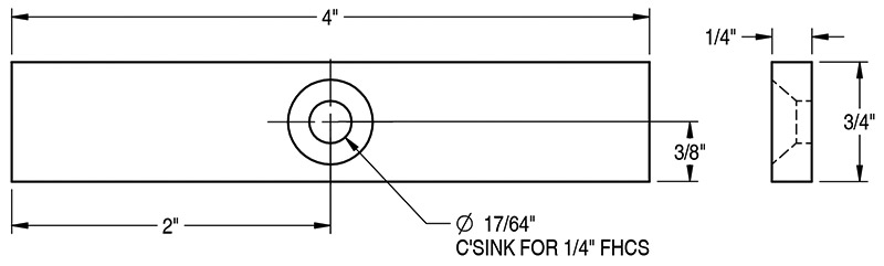
The two side supports are optional. Each is a 4 × ¾ × ¼ in aluminium bar with a self-adhesive rubber foot, screwed through its centre hole into one of the front T-nuts, which Collier turns 90° in the slot. Swung down, they let the jig stand on its front edge with both faces of the board in reach (Figure 1), which helps with parts that have to be held from one side and soldered from the other. “The exact dimensions aren’t critical”, he writes, as long as the bar is thick enough to take a fully countersunk ¼ in screw. I have not fitted them.
2.6 The Plate and Foam
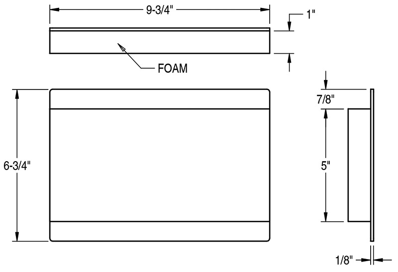
The plate is cut 9¾ × 6¾ in from ⅛ in aluminium. The foam is 1 in thick, cut to about 5 × 9¾ in so it fits loosely through the frame’s opening, and glued to the middle of the plate with 3M Super 77 spray adhesive.
The two ⅞ in strips of bare plate are what make the jig work as it does. They land on the bottom faces of the frame’s long sides, so the plate stops at the frame and the foam is squeezed by a fixed amount: the 1 in of frame depth less the height of the parts. That is why the clamps only need to hold the plate on the frame, not squeeze it.
My foam is not glued. It lies on the parts and the plate goes on top of it (Volume 1, Figure 3), which makes it easy to swap a thick pad for a thin one between passes.
2.7 First Use
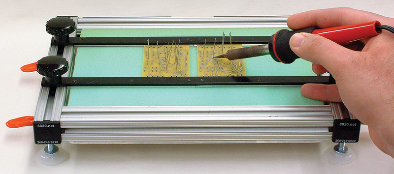
The sequence is in Volume 1. Two set-up checks are worth making on a new jig. First, put a bare board in the rails, clamp the plate down without foam, and turn the jig over: the board should sit flat on both ledges along its whole length, with no rattle. A board that rocks means the notches are deeper than the board is thick, and a shim strip or a shallower notch fixes it. Second, with the foam fitted and no board, the plate should come down onto the long sides with the clamps closing easily; if the clamps have to fight, the foam is too thick or too firm.
Collier found three limits in use. A terminal block “was too large to be clamped with foam, had leads that were too short to bend, and didn’t respond well to superglue”, and some large or odd-shaped parts simply had to be held by hand. The jig is also sized for small boards. Volume 3 works out why a much larger board bows in the middle of a jig like this, and designs one for boards up to 300 × 400 mm that does not.
2.8 My Build
I built mine to these drawings, with the small changes noted above: rails from the two-strip alternate rather than milled, star knobs in place of Collier’s knobs (¼-20, from my own stock or eBay), clamps on adapter plates, foam loose rather than glued, no side supports.
Sources
- John D. Collier, “Build A Circuit Board Assembly Jig”, Nuts and Volts, September 2011, nutsvolts.com/magazine/article/september2011_Collier: text, Table 1 and Figures 1 to 8.
- My jig: my photos, 7 November 2026 (Volume 1).
2.9 Printable Bill of Materials
PCB Soldering Jig — Collier 2011 build BOM (PDF)
Next — Volume 3: A Big One. Why a 300 mm board bows in the middle of this jig, worked out with numbers, and a larger jig for boards up to 300 × 400 mm that does not: stiffer rails, support bridges under the board, a stiffened plate and deeper foam.
Comments (0)