Pcb Soldering Jig · Volume 3
A Big One: 300 × 400 mm Without the Bow
3.1 The Brief
My Collier jig is sized for small boards, and it does them well. I want a much larger one that will take a board up to 300 × 400 mm and will not bow in the middle. This volume works out why a jig of this kind bows when it is simply scaled up, and designs one that does not. It is a proposal: nothing here is built yet.
3.2 Why a Bigger Jig Bows
Four things in the jig carry the foam’s push, and each can bend: the board between the rails, the rails between their knobs, the plate between its clamps, and the frame. The foam pushes on the parts with a pressure set by how far it is squashed. Soft polyurethane foam of the craft-shop kind gives a few kilopascals at 40% compression; the softest band in the ISO 3386 grading of foams starts at 2 kPa (GMW14196 summary). A kilopascal does not sound like much, but over a 300 × 400 mm board 5 kPa is 600 N, the weight of about 60 kg, and it all has to go somewhere.
The trouble is how fast bending grows with span. For a beam or a plate loaded evenly along its span, the sag in the middle goes up with the fourth power of the span. Doubling the distance between supports makes the sag sixteen times bigger. A jig that is fine at 125 mm is in trouble at 300 mm, and nothing about the small jig gives warning.
The numbers below are simple beam theory, worked in this project’s bow_calcs.py with FR-4’s flexural modulus of about 18 GPa crosswise (Gund Co. NEMA FR4 sheet) and aluminium’s 69 GPa. They are conservative, because they treat each span as simply supported.
The board. A 1.6 mm board held only by its two edges, sagging under the foam:
Table 1 — The board. A 1.6 mm board held only by its two edges, sagging under the foam
| Span between supports | at 1 kPa | at 2 kPa | at 5 kPa |
|---|---|---|---|
| 60 mm (a µKENBAK-1-sized board) | 0.03 mm | 0.05 mm | 0.14 mm |
| 127 mm (the biggest board in Collier’s jig) | 0.55 mm | 1.1 mm | 2.8 mm |
| 300 mm (the new jig, rails only) | 17 mm | 34 mm | 86 mm |
The last row is past the point where beam theory means anything literal: the board simply bows until the foam stops pushing, and the parts in the middle are barely held. That is the bow. No stiffening of the frame fixes it, because the board itself is what bends. The board needs support in the middle, from the solder side, against the foam.
With a support line every s millimetres instead:
Table 2 — With a support line every s millimetres instead
| Support spacing | at 2 kPa | at 5 kPa |
|---|---|---|
| 75 mm | 0.13 mm | 0.34 mm |
| 100 mm | 0.42 mm | 1.1 mm |
| 133 mm | 1.3 mm | 3.3 mm |
A support every 100 mm, with soft foam, keeps the board within half a millimetre; a continuous board over several supports does better than these simple spans by about half again.
The plate. Collier’s ⅛ in plate, scaled to 0.32 × 0.44 m and held only at its ends, would sag 11 mm under 600 N. A ¼ in plate sags 1.4 mm. A ¼ in plate with two 1 in extrusions bolted along it sags 0.2 mm; three, less.
The rails. Collier’s rails, two ⅛ × ½ in strips, carrying one edge of a 300 × 400 board over 0.44 m, would sag 18 mm. A rail of 1 in square T-slot extrusion (moment of inertia about 0.046 in⁴; IPS catalogue) sags 0.25 mm under the same load, and much less once the bridges take most of it.
The frame. The frame mostly carries its loads in short paths: the clamps pull the plate toward the frame at the same places the rail knobs pull the rails the other way. Put the clamps in line with what they react against, and the frame carries little bending. A deeper section (1 × 2 in on edge, 0.321 in⁴; TNUTZ EX-1020) is chosen for depth and handling rigidity more than for strength.
3.3 The Design
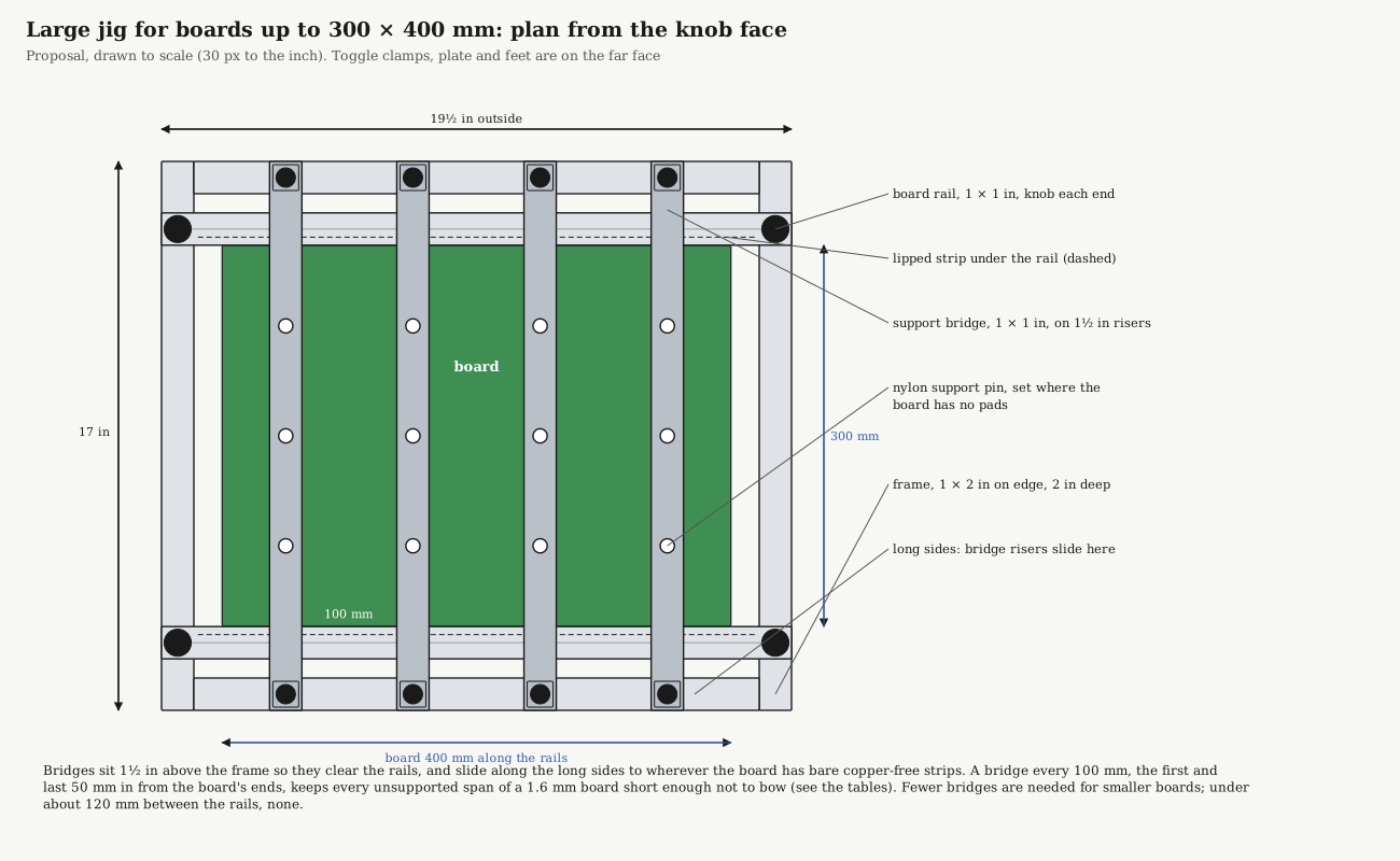
The design keeps everything that makes Collier’s jig work: the lipped rails, the knob adjustment, the foam pad on a plate that seats on the frame, the toggle clamps, the levelling feet. It changes four things.
- Support bridges under the board. Four bars of 1 in extrusion cross the frame on the knob face, standing on 1½ in risers so they clear the rails. Each slides along the long sides and is locked by a knob at each end. Each carries three nylon support pins, ¼-20 nylon thumb screws in T-nuts in the bridge’s underside slot, screwed down until they just touch the board’s solder side. Set them on bare board: an unused area, a mounting-hole pad, the strip between two rows of parts. With bridges at 50, 150, 250 and 350 mm along a 400 mm board, no unsupported span is longer than 100 mm. A smaller board takes fewer bridges; at under about 120 mm between the rails it needs none, which is the small jig’s case.
- Rails of 1 in extrusion in place of flat bar. Each rail is a 19½ in length of 1010 with a lipped aluminium strip screwed under it between the end pieces, its ledge along the inner edge, ¼ in proud of the rail. That keeps the lip exactly as in the original, on a rail that cannot bend.
- A deeper frame and deeper foam. The frame is 1 × 2 in extrusion on edge, 2 in deep, and the foam pad is 2 in thick. The plate still seats on the frame’s long sides, so the frame still sets the squeeze; but a 12 mm capacitor in 50 mm of foam is a 24% squeeze, against 47% in 25 mm. The pressure on a mixed board stays lower and more even, which matters more on a big board where the parts are of every height.
- A stiffened plate. A ¼ in aluminium plate, 16½ × 17¼ in, carries three 1 in extrusions bolted along its outer face: one over each long side and one down the middle. Six toggle clamps, three on each end piece, press the bare ends of the plate just beyond each stiffener, so each stiffener is a beam between two clamps.
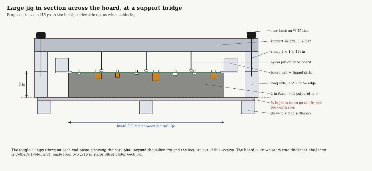
The jig now has things standing off both faces: bridges and knobs about 3½ in on the knob face, clamps and stiffeners on the plate face. It stands on four corner standoffs on each face, short lengths of 1 in extrusion tapped ¼-20 at both ends, screwed into T-nuts on a stud and finished with a levelling mount: about 4 in on the knob face and 2½ in on the plate face, cut to suit the clamps chosen.
The board’s area is about four times that of the largest board Collier’s jig takes, and the jig is heavier to match: the plate alone is about 7 lb of aluminium. Turning it over is a two-handed job. A jig this size is also a candidate for the trick in my Crossbar Rotating Stand, in this same Jigs and Fixtures group: stub shafts in the two end pieces and a pair of uprights, so it turns over on its own axis instead of being lifted.
3.4 Dimensions
Table 3 — Dimensions
| Item | Size | Notes |
|---|---|---|
| Largest board | 300 × 400 mm, 1.6 mm | The standard thickness, kit boards included; the ledge is sized for it. A board of another thickness would need its own pair of strips |
| Frame outside | 19½ × 17 × 2 in | Long sides 17½ in between two 17 in end pieces, 1020 on edge |
| Frame opening | 17½ × 15 in (445 × 381 mm) | Clears the board, the foam and the rails |
| Board rails | 1010, 19½ in | Knobs ½ in from each end, on the end pieces; inner faces from about 50 mm to 325 mm apart |
| Lipped strips | two 1/16 × ¾ in per rail, 17¼ in | Offset 1/16 in to form the ledge, ¼ in proud of the rail’s inner face; or one ⅛ in bar with Collier’s milled 0.075 × 0.060 in rebate |
| Bridges | 1010, 17 in, four | On 1½ in risers of 1010; nylon pins ¼-20 × 2 in, three per bridge to start |
| Plate | ¼ in 6061, 16½ × 17¼ in | Seats ¾ in on each long side |
| Stiffeners | 1010, 15¼ in, three | Leave 1 in of bare plate at each end for the clamps |
| Foam | 2 in soft polyurethane, about 12 × 16 in | Glued to the plate, or loose like mine; a 1 in layer on top for passes of low parts |
| Toggle clamps | six | On adapter plates on T-nuts, so each can slide to line up with a stiffener |
3.5 Building It
The frame goes together as Collier’s does (Volume 2), with two connectors at each corner because 1020 has two centre holes: tap both holes in each end of the long sides ¼-20, drill two access holes in each end piece, and load every T-nut before closing the frame. That is the four rail knobs and the eight bridge risers on the knob face, the six clamp adapter plates on the plate face, and the eight corner standoffs, four on each face.
The lipped strips are made the way I made the small jig’s rails, with Collier’s no-mill alternate: for each rail, two 1/16 × ¾ in strips 17¼ in long, the lower one standing 1/16 in proud of the upper along the inner edge, so that its edge is the ledge the board sits on. A 1/16 in (1.6 mm) step suits standard 1.6 mm boards, kit boards included. Collier’s milled version, a 0.075 × 0.060 in rebate in a single ⅛ × ¾ in bar, does the same job for anyone who prefers to mill it. Screw each pair to the underside of its rail with 10-32 screws into the rail’s slot, set ¼ in proud of the rail’s inner face; over 17¼ in the strips want a screw every 3 in or so to keep them pulled flat together.
The bridges and risers need a 17/64 in hole through each end of each bridge and down the centre of each riser for the knob studs. The plate needs twelve countersunk holes for the stiffener screws, so its foam face stays flat.
Then the set-up checks from Volume 2, plus one: with a bare board in the rails and the bridges’ pins backed off, clamp the plate down over the foam and turn the jig over. Run the pins down until each just touches; a straightedge across the board should then show it flat to the rails.
3.6 Using It
The routine is the small jig’s, with one step added after the board goes in: set the bridges. Slide each one to where the board has a strip without pads, set its pins on bare board, and lock it. For a board with parts on both faces, the bridges are on the side being soldered; between passes they move to new places, one at a time.
When soldering, the bridges are 1½ in above the board, high enough for an iron to reach under at an angle. A joint directly under a bridge is easier to reach with that bridge slid a little along; the board stays supported by its neighbours while one bridge moves.
3.7 Parts
Table 4 — Parts
| Part | Qty | Notes |
|---|---|---|
| 1 × 2 in T-slot extrusion (80/20 1020 or equal) | 2 × 17½ in, 2 × 17 in | Frame |
| 1 × 1 in T-slot extrusion (80/20 1010 or equal) | 2 × 19½ in, 4 × 17 in, 3 × 15¼ in, 8 × 1½ in, 4 × 4 in, 4 × 2½ in | Rails, bridges, stiffeners, risers, standoffs |
| Anchor fasteners (end connectors) | 8 | Two per frame corner |
| ¼-20 T-nuts, 10 series | about 60 | Rail knobs 4, risers 8, clamp plates 12, standoffs 8, stiffeners 12, pins 12, spares |
| 10-32 T-nuts and flat-head screws, 10 series | 12 | Lipped strips to rails, six per rail |
| Star knobs, ¼-20, with studs or on threaded rod | 12 | Four for the rails, eight for the bridges |
| Nylon thumb screws, ¼-20 × 2 in, with nylon jam nuts | 12, and spares | Support pins |
| Levelling mounts, ¼-20 stud | 8 | Four on each face |
| Horizontal toggle clamps, with adapter plates | 6 | Collier’s FC-20 / 205-S class |
| 6061 aluminium plate, ¼ in | 16½ × 17¼ in | Pressure plate |
| 6061 aluminium flat bar, 1/16 × ¾ in | 4 × 17¼ in | Lipped strips, two per rail (or 2 × ⅛ × ¾ in to mill) |
| ¼-20 flat-head screws | 12 | Stiffeners to plate |
| Soft polyurethane foam, 2 in and 1 in | about 12 × 16 in each | Craft shop or upholstery foam |
The sizes are in inches because the small jig is built in inch 80/20, but nothing depends on it: 25 mm and 25 × 50 mm metric profiles do the same job, with the cut lengths converted and the stiffness checked against the maker’s sheet. The 1/16 in strips are the one dimension to keep, or replace with 1.6 mm metric strip. The printable BOM below has the same parts with quantities, alternates and places to buy them.
Sources
- The base design: John D. Collier, “Build A Circuit Board Assembly Jig”, Nuts and Volts, September 2011, nutsvolts.com/magazine/article/september2011_Collier.
- Bending calculations:
03-outputs/calcs/bow_calcs.pyin this project, simple beam theory with the inputs below. - FR-4 flexural modulus, 2,900 ksi (20 GPa) lengthwise and 2,600 ksi (18 GPa) crosswise at 0.062 in: Gund Co. NEMA FR4 sheet.
- 1 × 2 in T-slot moments of inertia, 0.087 and 0.321 in⁴: TNUTZ EX-1020. 1 × 1 in profile, about 1.91 cm⁴ (0.046 in⁴): Industrial Profile Systems inch catalogue. Check the chosen maker’s figures before building.
- Foam firmness bands at 40% compression (ISO 3386): GMW14196.
- The rotating-stand idea: Crossbar Rotating Stand, Jigs and Fixtures, this site.
Comments (0)